Anchor

a self-drilling, anchor technology, applied in the direction of fastening means, dowels, mechanical equipment, etc., can solve the problems of anchor breaking during the installation of drywall, requiring a high installation torque for the internal fastener, and difficulty in mounting articles thereto, so as to achieve excellent results, increase the pullout strength of the anchor, and increase the strength

Active Publication Date: 2007-09-27
ILLINOIS TOOL WORKS INC
View PDF19 Cites 7 Cited by
  • Summary
  • Abstract
  • Description
  • Claims
  • Application Information

AI Technical Summary

Benefits of technology

The patent text states that the distance between the slits on an anchor and the flanged rear end can affect its pullout strength. When this distance is between 1/16 and 1/2 inches, the anchor becomes stronger. The text also mentions that the best results are achieved when the distance is around 0.189 inches.

Problems solved by technology

The technical problem addressed in this patent text is the difficulty of mounting articles to drywall because of its friable nature. Previous methods, such as self-drilling anchors and splitting anchors, have had limitations in pull-out strength and may have caused damage to the drywall. Toggle bolts, which are heavy duty anchors, are expensive, unreliable, and difficult to install. There is a need for an anchor that is easier to install, more reliable, and generates increased pull-out strength over existing anchors.

Method used


Image

  • Anchor
  • Anchor
  • Anchor

Examples


Embodiment Construction

[0021] The description provided herein incorporates by reference the description provided in the commonly assigned U.S. patent application Ser. No. 11 / 290,212, filed one Nov. 30, 2005. In that application, certain characteristics of a desirable anchor were disclosed. These are shown in this application as well, but with different reference numerals, having either a 200 or 300 prefix, to help distinguish this case from previous ones, even though there may be intentional overlap of elements.

[0022] Whereas in a previous application, other dimensions were mentioned in regards to another embodiment, the embodiments presented in the current application may have differed in order to achieve increased pull-out strength.

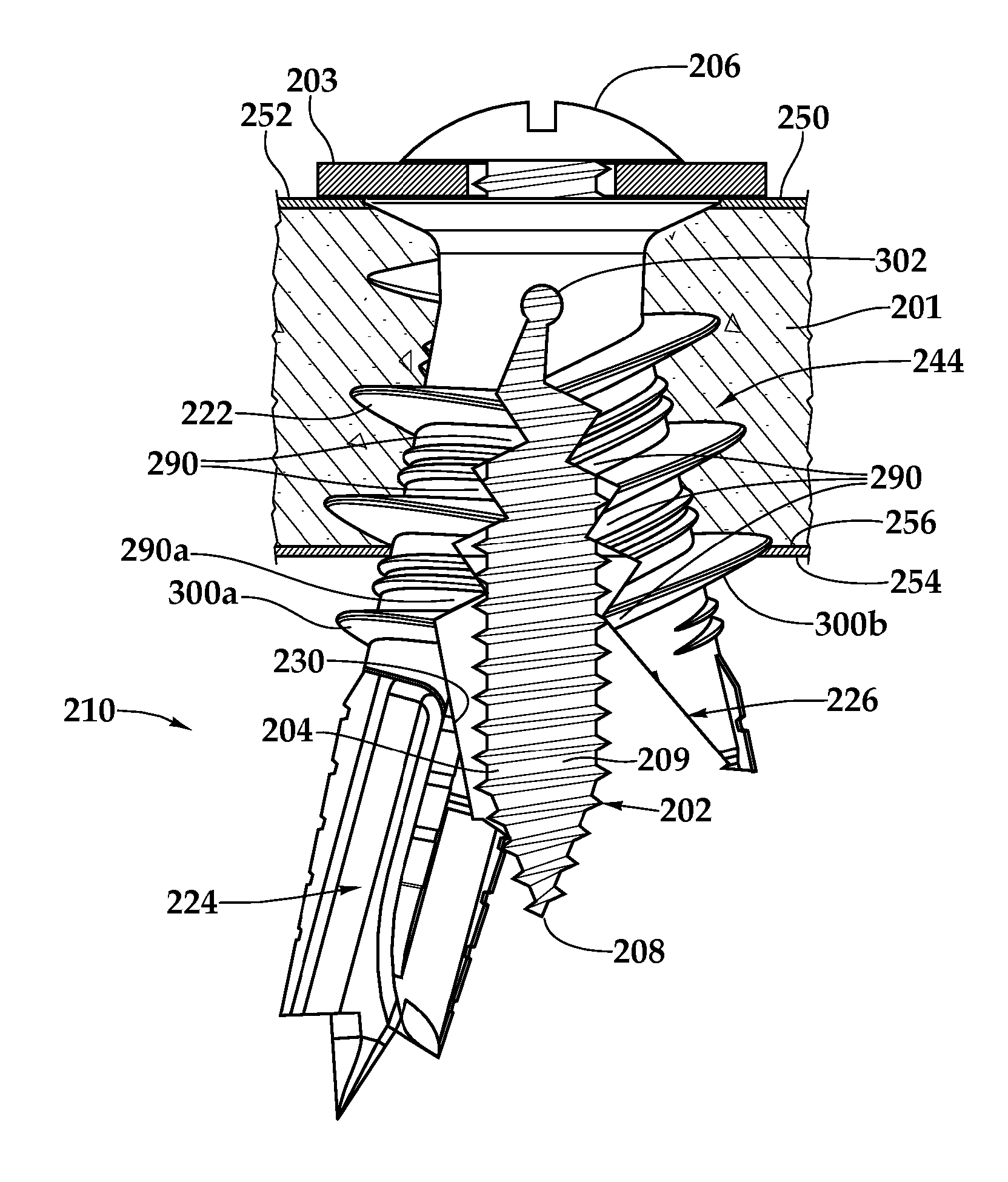
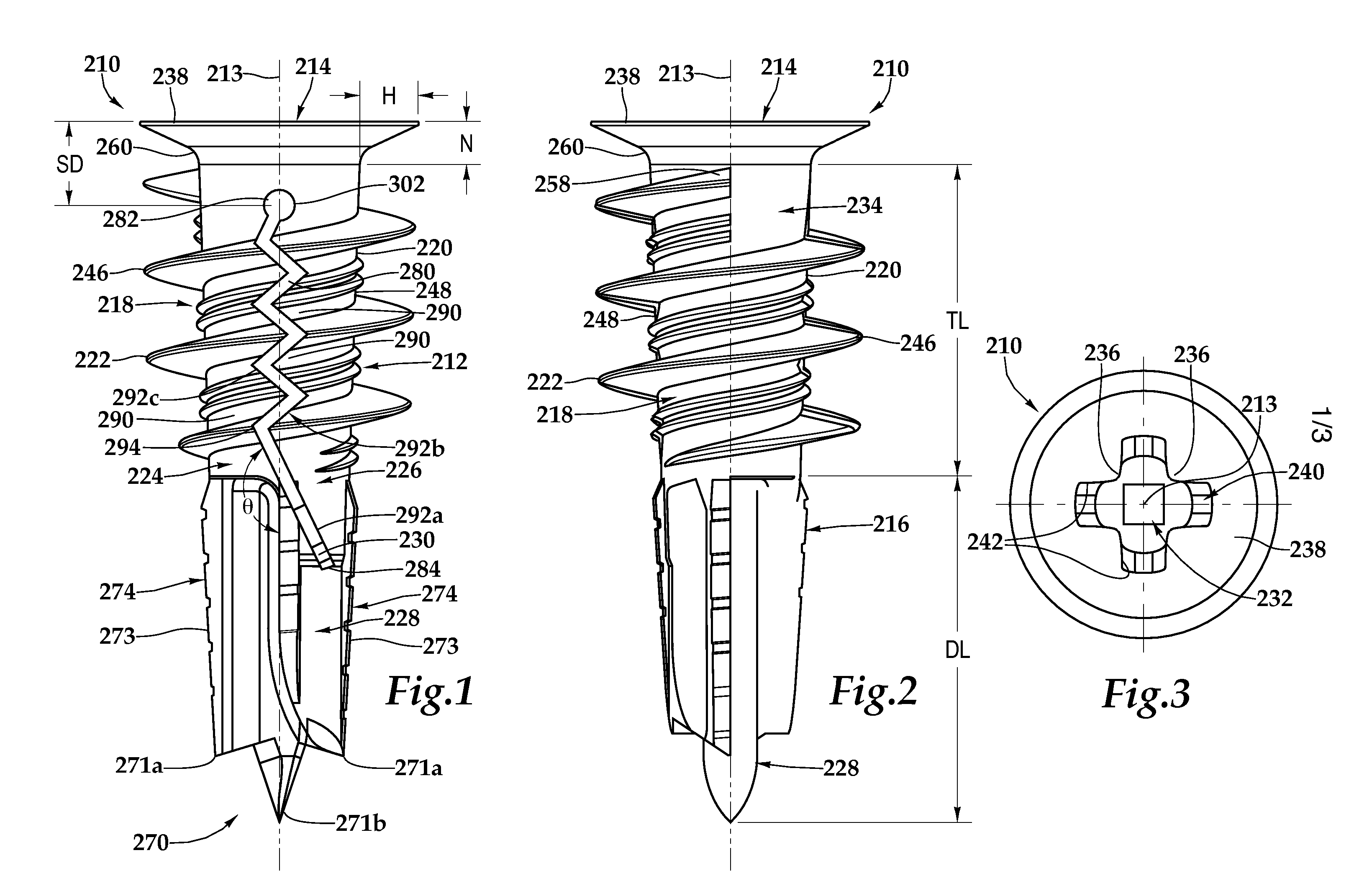
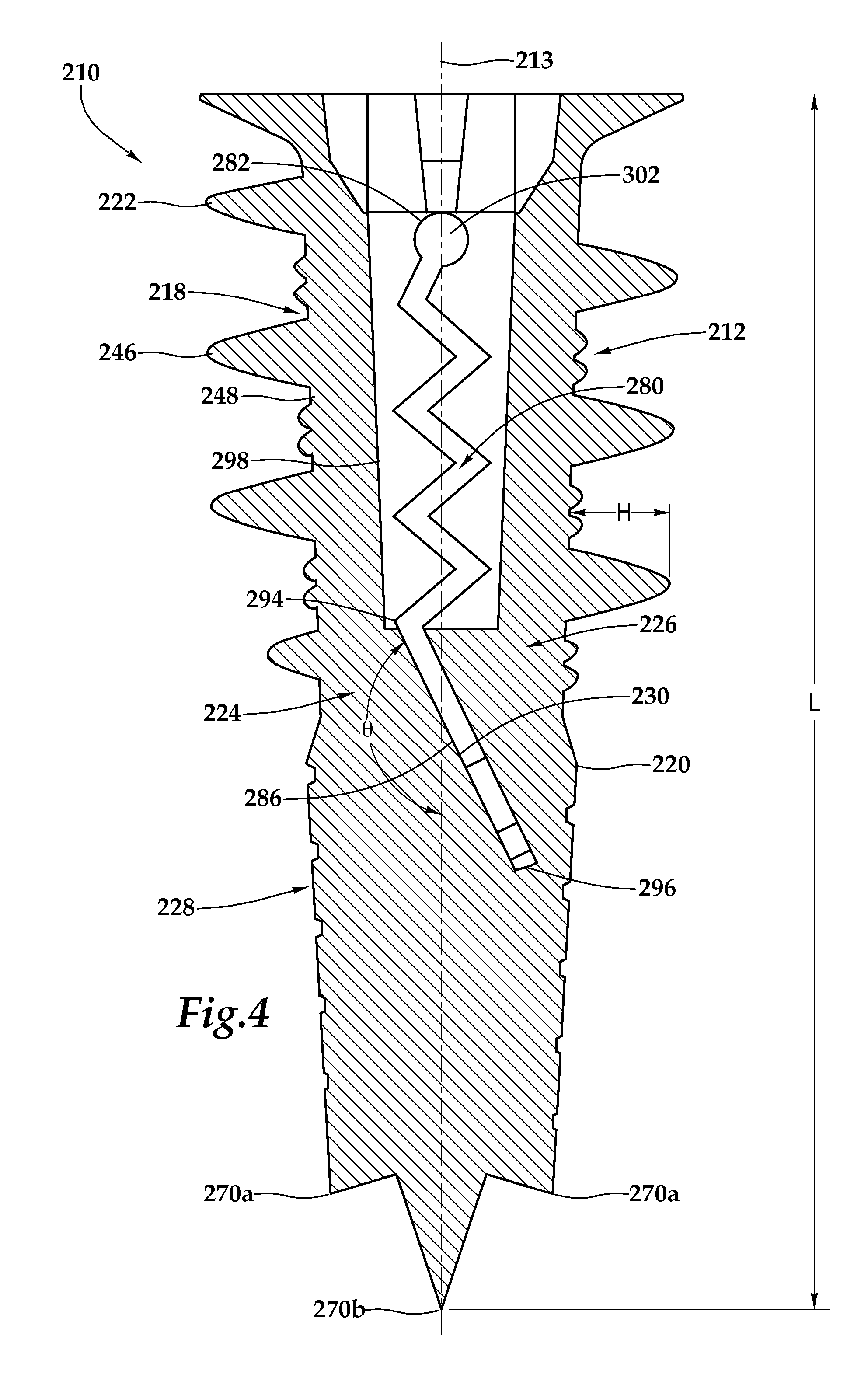
[0023] Referring to FIGS. 1, 5 and 6, a self-drilling anchor 210 is shown for use in a friable material, such as drywall 201. Anchor 210 includes a body 212 having an axis 213, a flanged rear end 214 having torque transmitting surfaces 242, a drilling front end 216, an oute...


PUM


Abstract

A self-drilling anchor for use in a friable material comprises a body having an axis, a flanged rear end, a drilling front end and a generally cylindrical portion therebetween having an outer surface with a thread disposed thereon, wherein the body forks, beginning at a predetermined distance from the flanged rear end, into a first leg and a second leg, the first leg extending forwardly into a drilling tip, wherein the first leg may have a generally rearward facing shoulder angled obtusely outwardly with respect to the axis, wherein the body has an axial bore for receiving an elongate fastener, the axial bore extending substantially through the flanged end and leading to the generally rearward facing shoulder, wherein the anchor is adapted so that the first leg pivots apart from the second leg when the elongate fastener deflects the generally rearward facing shoulder and the predetermined distance is selected to increase pullout strength when the first leg is pivoted apart from the second leg and the anchor is installed in the friable material.

Description


Claims


Application Information

Patent Timeline
Owner ILLINOIS TOOL WORKS INC
Why Eureka
Try Eureka