Apparatus, methods and computer program products providing signaling of time staggered measurement reports and scheduling in response thereto

a technology of time-staggered measurement and reporting, applied in the field of measurement reporting techniques, can solve the problems of large uplink signaling bandwidth, excessive and unrealistic amount of uplink signaling bandwidth, and brute force cqi signaling approach

Inactive Publication Date: 2007-09-27
NOKIA CORP
View PDF3 Cites 38 Cited by
  • Summary
  • Abstract
  • Description
  • Claims
  • Application Information

AI Technical Summary

Benefits of technology

This patent describes methods for evaluating the quality of multiple channels (such as websites or social media accounts) based on their performance over time. By measuring these performances regularly and providing feedback about them, administrators can better manage and improve the overall quality of the channel(s). One technical effect of this approach is improved user experience: if users are able to access high-quality content consistently through various channels, they may be more likely to engage with it and become regular customers. Another benefit is resource allocation: instead of simply identifying which channels have poor performance, administrators can use the evaluation results to allocate limited resources effectively among all the channels. Overall, this system helps ensure continuous improvement and optimal utilization of network assets.

Problems solved by technology

The technical problem addressed by this patent is how to efficiently transmit data on the uplink signaling between a base station and a user device during communication over a wireless network without consuming too much resources or causing delays. Specifically, the issue relates to the transmission of channel quality indicators (CQIs) reported by the user devices, which require a significant amount of uplink signaling bandwidth if transferred directly.

Method used


Image

  • Apparatus, methods and computer program products providing signaling of time staggered measurement reports and scheduling in response thereto
  • Apparatus, methods and computer program products providing signaling of time staggered measurement reports and scheduling in response thereto
  • Apparatus, methods and computer program products providing signaling of time staggered measurement reports and scheduling in response thereto

Examples


Embodiment Construction

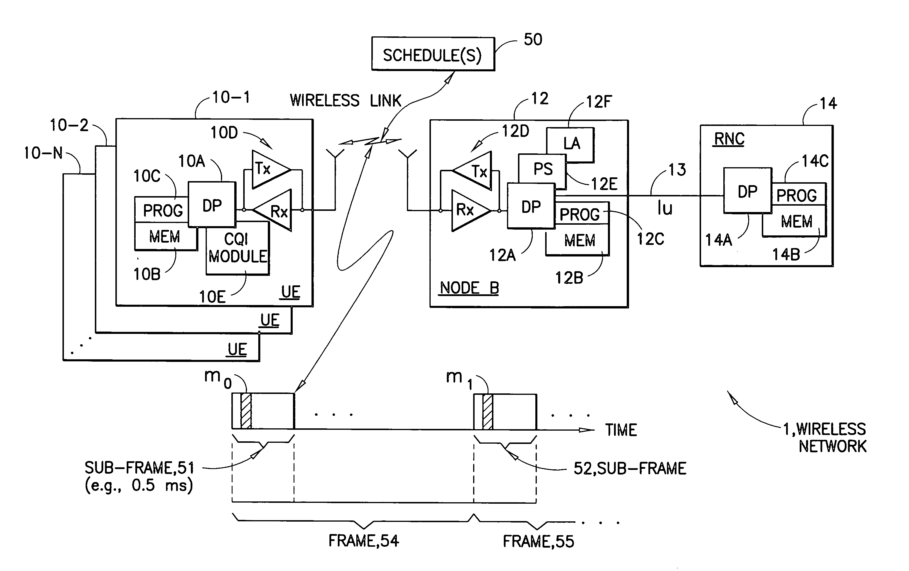
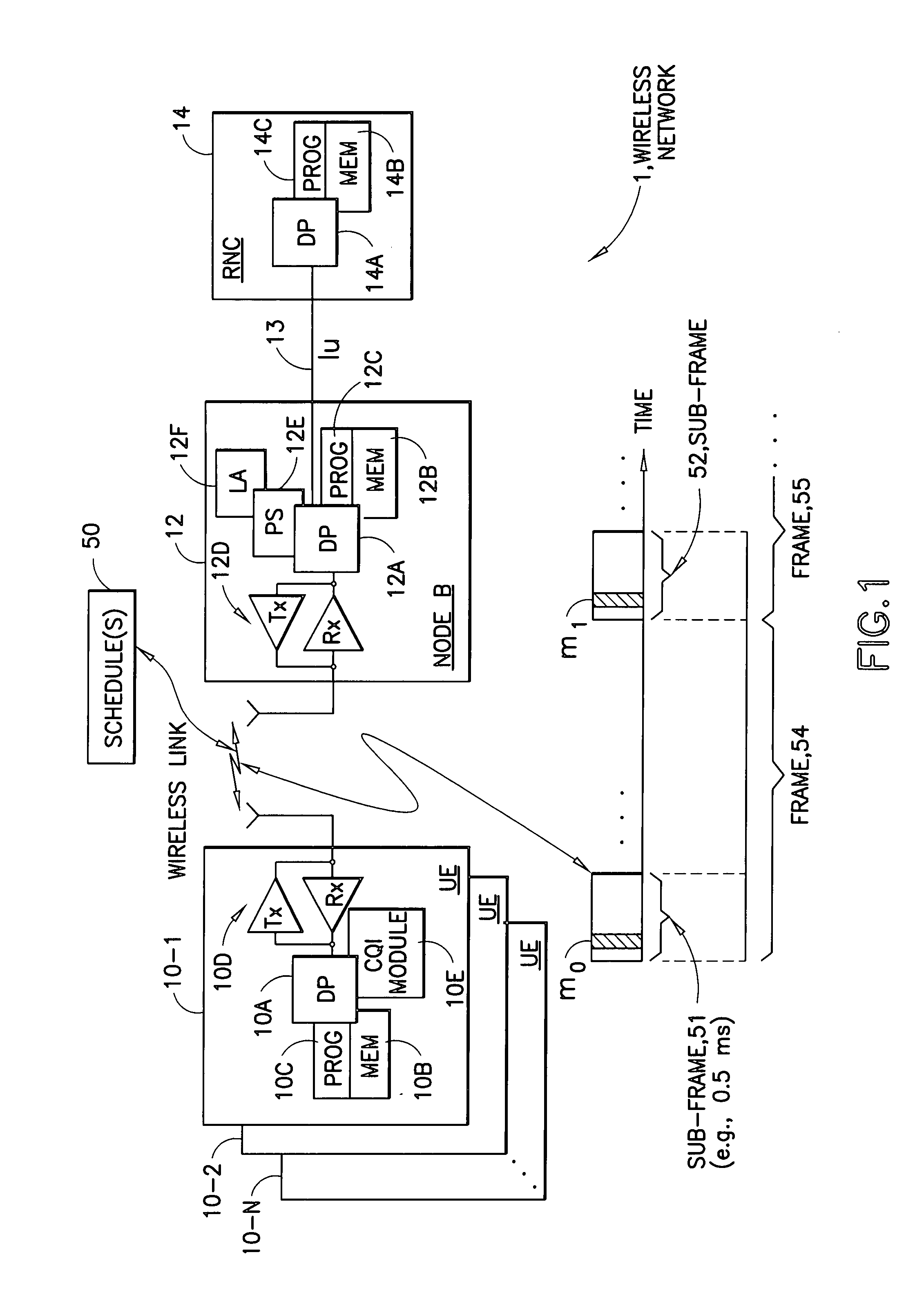
[0018] Reference is made first to FIG. 1 for illustrating a simplified block diagram of various electronic devices that are suitable for use in practicing the exemplary embodiments of this invention. In FIG. 1, a wireless network 1 is adapted for communication with N UEs 10-1 through 10-N via a Node B (e.g., a base station) 12. The network 1 may include a serving RNC 14, or other radio controller function. The UE 10-1 includes a data processor (DP) 10A, a memory (MEM) 10B that stores a program (PROG) 10C, and a suitable radio frequency (RF) transceiver 10D (having a receiver, Rx, and a transmitter, Tx) for bidirectional wireless communications with the Node B 12, which also includes a DP 12A, a MEM 12B that stores a PROG 12C, and a suitable RF transceiver 12D (having a receiver, Rx, and a transmitter, Tx). The UEs 10-2 through 10-N are expected to be similar to the UE 10-1. The Node B 12 may be coupled via a data path 13 (e.g., Iu) to a serving or other RNC 14. The RNC 14 includes a...


PUM


Abstract

A method includes determining a value representative of an overall quality of a set of channels and transmitting during a reporting interval an indication of the determined value. The method also includes determining at least one additional value representative of a quality of a subset of the set of channels, and transmitting in at least one subsequent reporting interval an indication of the at least one additional value. Another method includes receiving during a reporting interval an indication of a value representative of an overall quality of a set of channels and receiving during at least one subsequent reporting interval an indication of at least one additional value representative of a quality of a subset of the set of channels. The method further includes, using the values, scheduling resources associated with the channels in the set, and transmitting an indication of the scheduled resources.

Description


Claims


Application Information

Patent Timeline
Owner NOKIA CORP
Why Eureka
Try Eureka