Electromechanically driven external fixator and methods of use

a fixator and electronic technology, applied in the field of surgical orthopedic instruments and to the external fixation of bone fractures, can solve the problems of not being able to be progressively adjusted, requiring a significant amount of expertise and management, and no web based software program that can be used

Inactive Publication Date: 2007-09-27
ZIRAN BRUCE H +1
View PDF18 Cites 75 Cited by
  • Summary
  • Abstract
  • Description
  • Claims
  • Application Information

AI Technical Summary

Problems solved by technology

The problems expressed with fixation in the late 20th century, however, were mostly due to lack of understanding about its basic principles of application and healing.
However, due to its completely manual nature, it required a significant amount of expertise and management.
Subsequently, many surgeons in the United States did not employ the device routinely.
These are not progressively adjustable like the struts of the Taylor Frame, and there is no web based software program that can be used.
Still, these devices require experience for correct placement and are manually driven.
If the construct is made too flexible, too early, the resultant strain may exceed the limits of that callous.
And if there is not insufficient EF load transfer, some bone resorption and disuse osteopenia may result, both of which are undesirable.

Method used


Image

  • Electromechanically driven external fixator and methods of use
  • Electromechanically driven external fixator and methods of use
  • Electromechanically driven external fixator and methods of use

Examples


Embodiment Construction

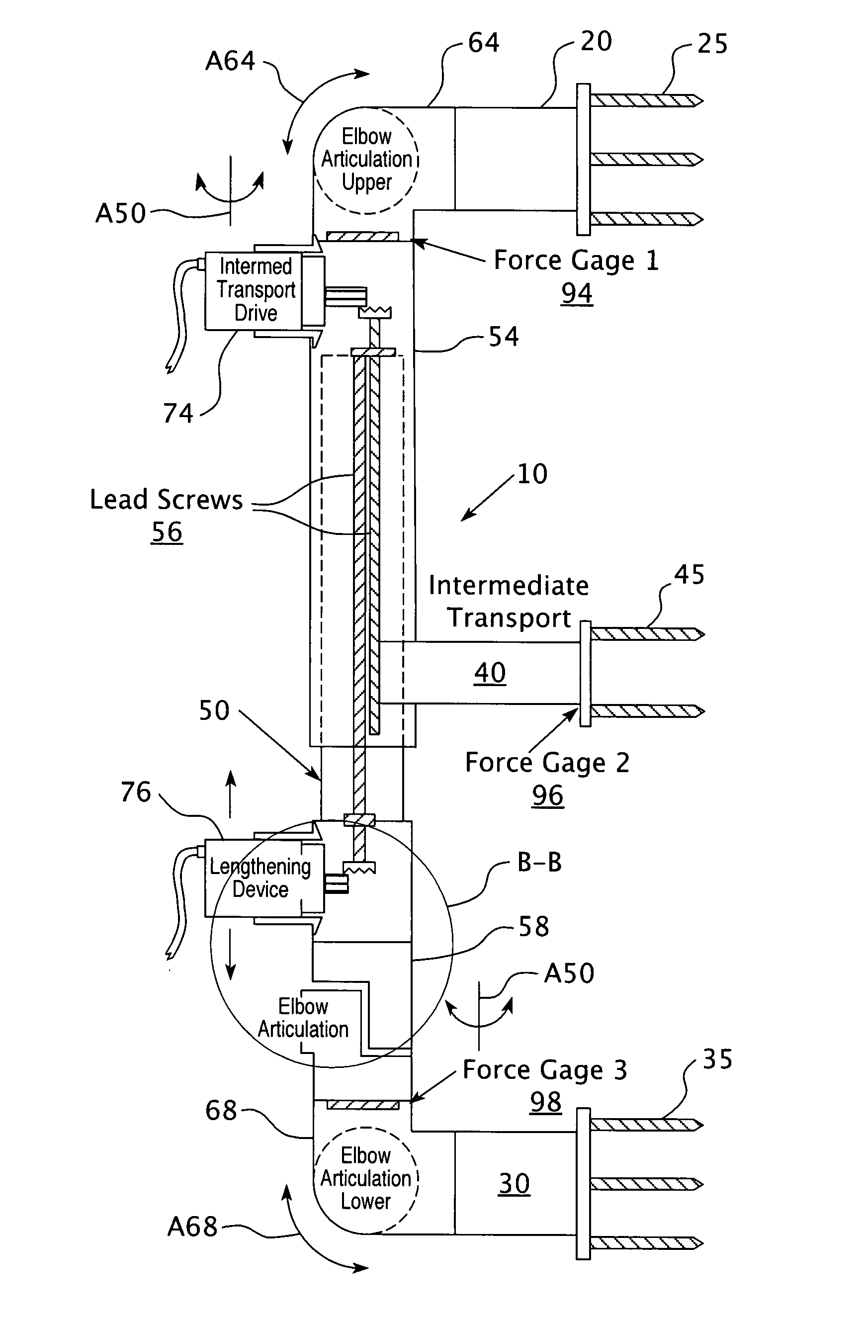
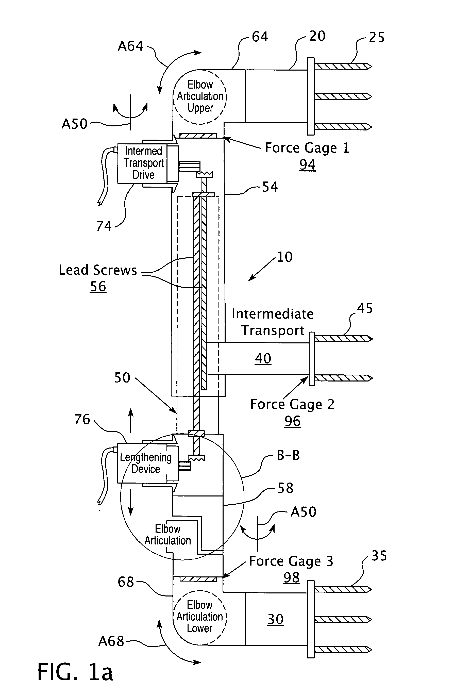
[0027]As described herein below, the term “positioning” is also meant to expressly address the need for subsequent bone “re-positioning” as well. And, while repeated references are made to uses to repair fractured bone by the methods and apparatus of this invention, it should be equally understood to address beyond “broken bone” repairs, the possibilities for both mal-union and non-union, or as a slow bone correcting device. (i.e. the purposeful correction of misaligned or non-healed bones). The deformity of the bone would be an independent variable, and its correction would be such to place it in an anatomic or mechanical axis. The gradual correction would occur in multiple planes and be driven by the coordinated movements of each electromechanical component. In addition, using the same electromechanical elements, the external fixator can be used for intentional compression to stimulate partially healed bone. Furthermore, in the event of missing sections of bone, the device can be ...


PUM


Abstract

A device for electromechanically and / or electro-pneumatically positioning a fractured bone having a first clamping unit adapted for attachment to the bone by at least one first bone fastener, a second clamping unit adapted for attachment to the bone by at least one second bone fastener, and at least one of: (i) a translation component operatively driven by a translational driver for relative translational movement of one clamping unit with respect to the other along a translational axis; (ii) an angulation component operatively driven by an angulational driver for relative angulational movement of one clamping unit with respect to the other along an articulation axis; and (iii) a rotational component operatively driven by a rotational driver for relative rotational movement of one clamping unit with respect to the other along a rotational axis.

Description

CROSS-REFERENCE TO RELATED APPLICATIONS[0001]This application claims the benefit of priority to U.S. Provisional Application Ser. No. 60 / 785,240, filed on Mar. 23, 2006 and fully incorporated by reference herein.FIELD OF THE INVENTION[0002]The present invention relates to surgical orthopedic instrumentation and to the external fixation of bone fractures. More particularly, this invention relates to electromechanical means for making automatic, multiple axis, multi-dimensional adjustments to bone fractures.BACKGROUND OF THE INVENTION[0003]External fixators have been in use for over a century. The first recorded use was by Wilhelm Wutzer (1789-1863) who used pins and an interconnecting rod in a clamping system to repair badly broken bones. Parkhill (1897) and Lambotte (1900) used unilateral devices with four pins and a bar / clamp system. By the 1960's, Vidal and Hoffman popularized using external fixators for open fractures and infected pseudarthroses. The problems expressed with fixat...

Claims


Application Information

Patent Timeline
Patent Type & Authority Applications(United States)
IPC IPC(8): A61B17/00
CPCA61B17/66A61B2019/464A61B2017/00544A61B2017/00017A61B2090/064
Inventor ZIRAN, BRUCE H.PERALA, BRIAN S.
Owner ZIRAN BRUCE H
Why Eureka
Try Eureka