Fastening system for internal fixation

a technology of internal fixation and fastening, which is applied in the field of system for internal fixation of bones, can solve the problems of fracture non-union, screw threads that cannot find adequate purchase in the bone to hold the bone, and each of these steps is complicated, and achieve the effect of optimizing fracture reduction

Active Publication Date: 2007-09-27
BIOMET CV
View PDF37 Cites 29 Cited by
  • Summary
  • Abstract
  • Description
  • Claims
  • Application Information

AI Technical Summary

Benefits of technology

[0013] The present invention contemplates a method for fixation of a bone fracture that comprises positioning a bone plate on a proximal surface of the bone, the bone plate including a plurality of openings therethrough and passing at least two elongated tension elements through plate openings and through the bone to a distal surface thereof. Each tension elements is anchored to the distal surface of the bone and then placed in tension. The proximal end of the tension element is then anchored to the bone plate while maintaining the tension in the element. To facilitate passage of each tension element through the bone, a K-wire or stylet may be used to form an appropriately oriented path and a sheath may be used to help convey the tension element, and in some cases the distal anchor, through the bone.
[0032] One significant benefit of the fracture fixation system of the present invention is that it is well suited for use in soft, osteopenic bone that is otherwise incapable of supporting a lag screw. At the same time, the tension elements provide a lag effect for optimal fracture reduction.
[0033] Another benefit is that the tension elements and anchors may be provided as “one size fits all”. In other words, once the tension elements are tensioned and anchored, any excess material is removed. The necessary size of the tension element need not be determined prior to implantation. The tension element may be arranged to pass directly across the bone or across long spans of the bone without requiring differently sized elements.
[0035] One significant benefit of the fracture fixation system of the present invention is that it is well suited for use in soft, osteopenic bone that is otherwise incapable of supporting a lag screw. At the same time, the tension elements provide a lag effect for optimal fracture reduction.
[0036] Another benefit is that the tension elements and anchors may be provided as “one size fits all”. In other words, once the tension elements are tensioned and anchored, any excess material is removed. The necessary size of the tension element need not be determined prior to implantation. The tension element may be arranged to pass directly across the bone or across long spans of the bone without requiring differently sized elements.

Problems solved by technology

Each of these steps is complicated when the bone has suffered multiple fractures or a fracture that is not simply transverse.
However, in less healthy (e.g., osteopenic) bone, the screw threads may not find adequate purchase in the bone to hold the bone and plate together in proper alignment.
This may result in non-union of the fracture that may require more invasive revision surgery to correct.
Another problem associated with screw fasteners is occasional breakage of the screw near the plate-bone interface due to stress concentrations arising from poor load sharing among all of the screws and / or high cyclic loading.
A further drawback of the screw fastener approach to internal fixation is that a large variety of screw sizes must be made available for each surgical procedure in order to accommodate variations in patient anatomy and fracture type.
Maintaining a large inventory of screw sizes, along with the appropriately sized drills, guides, drivers and fixtures, can be costly.
There is also the chance that an inappropriately sized screw may be selected during a procedure.
However, cerclage systems require access around the entire periphery of the bone so it is necessary for the surgeon to dissect soft tissues surrounding the bone.
Another problem is that the cerclage cable can exert significant line pressure against the periosteum, which may injure the bone and inhibit healing.

Method used


Image

  • Fastening system for internal fixation
  • Fastening system for internal fixation
  • Fastening system for internal fixation

Examples


Embodiment Construction

[0056] For the purposes of promoting an understanding of the principles of the invention, reference will now be made to the embodiments illustrated in the drawings and described in the following written specification. It is understood that no limitation to the scope of the invention is thereby intended. It is further understood that the present invention includes any alterations and modifications to the illustrated embodiments and includes further applications of the principles of the invention as would normally occur to one skilled in the art to which this invention pertains.

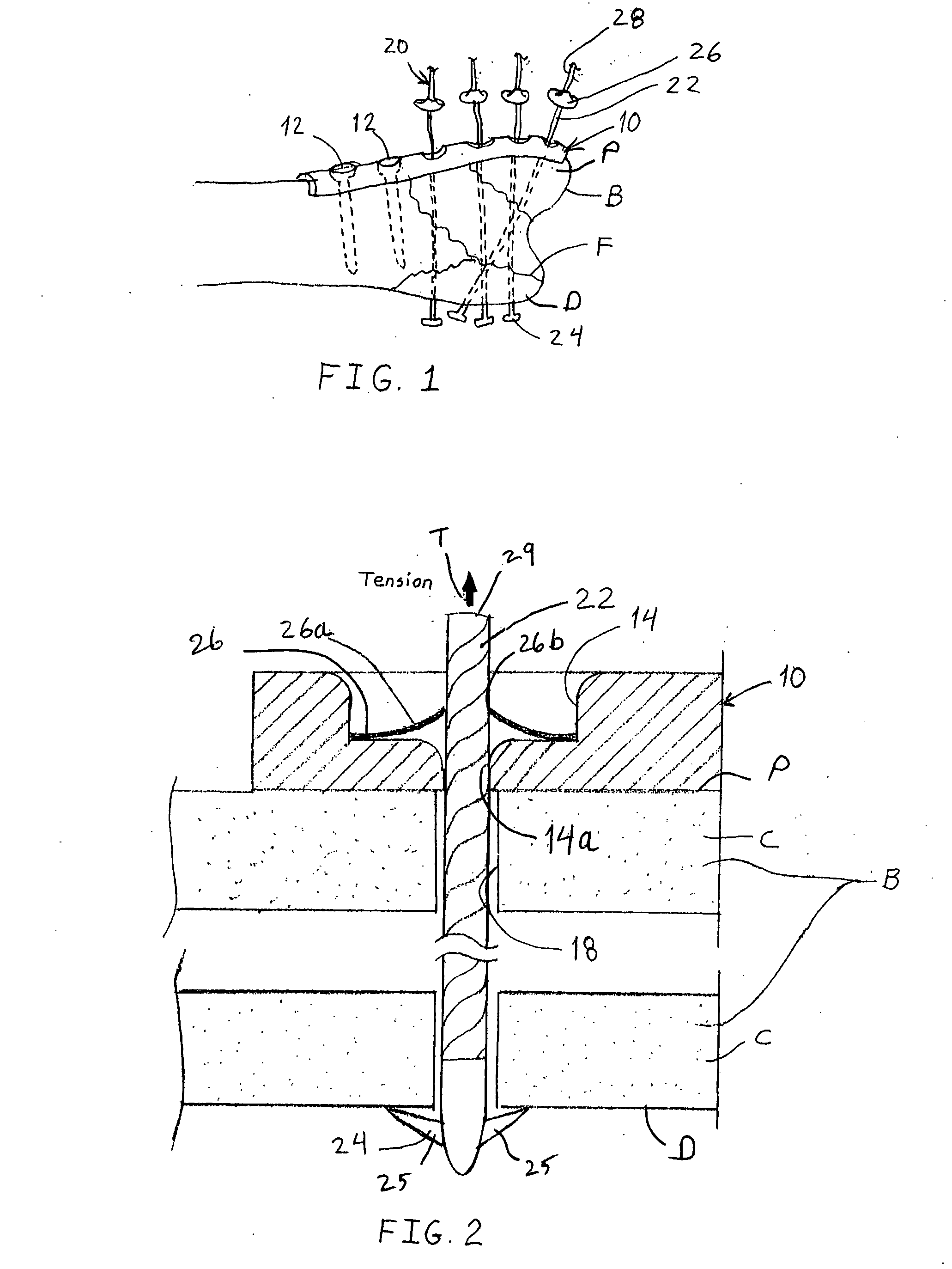
[0057] The present invention contemplates a system for reducing and fixing bone fractures, such as the fractures F in bone B shown in FIG. 1. The present system is particularly suited for fractures with multiple bone fragments that require precise reduction and secure fixation to maintain the reduction as the bone mends. In accordance with one embodiment, a bone plate 10 is positioned on the bone in a conventi...


PUM


Abstract

A bone fracture fixation system comprises a bone plate configured to bear against a proximal surface of the bone and a plurality of elongated tension elements, each sized to pass through an opening in the bone plate and through the bone from the proximal surface to a distal surface thereof. Each tension element is anchored to the bone and maintained in tension by a distal anchor attached to said tension element and configured to engage the distal surface of the bone and a proximal anchor engageable between the bone plate and the tension element. In one method for fixation of a bone fracture, the bone plate is positioned on a proximal surface of the bone while the tension element is introduced into the bone and through an opening in the bone plate from an opposite distal surface of the bone.

Description

BACKGROUND OF THE INVENTION [0001] The present invention relates to a system for internal fixation of a bone, and especially for the fixation of fractures of the bone. [0002] For any bone fracture, the orthopaedic specialist must first reduce the fracture and then adequately stabilize and fix the bone to maintain the reduction as the bone heals. Each of these steps is complicated when the bone has suffered multiple fractures or a fracture that is not simply transverse. Fractures of this type usually require some form of internal fixation to reduce and maintain the bone fragments. One conventional approach to reducing bone fragments is with a bone plate extending over a portion of the bone at the fracture site. In one surgical approach, an orthopaedic surgeon may use a specialized clamp applied across the bone while attaching the fixation plate to the bone by screwing a plurality of screw fasteners through holes in the plate into the underlying bone. [0003] Generally, screw fasteners...

Claims


Application Information

Patent Timeline
Patent Type & Authority Applications(United States)
IPC IPC(8): A61F2/30
CPCA61B17/1735A61B17/683A61B17/686A61B17/80Y10S606/916A61B17/8875A61B2017/00867A61B2019/464A61B17/88A61B2090/064
Inventor DEFFENBAUGH, DAREN L.SCHULZE, DALE R.
Owner BIOMET CV
Why Eureka
Try Eureka