
Video signal processing apparatus and control method thereof

a video signal and processing apparatus technology, applied in the field of video signal processing, can solve the problem of inconvenient user selection of desired channels, and achieve the effect of quick and convenient search of channel information

Inactive Publication Date: 2007-09-27
SAMSUNG ELECTRONICS CO LTD
View PDF5 Cites 8 Cited by
  • Summary
  • Abstract
  • Description
  • Claims
  • Application Information

AI Technical Summary

Benefits of technology

[0009]Accordingly, it is an aspect of the present invention to provide a video signal processing apparatus and a control method therefor including a UI (user interface) which is capable of variably displaying an arrangement of a plurality of channel informations so that the channel informations can move in a manner that corresponds to a moving instruction. Thereby, a user can rapidly and conveniently search the channel informations.
[0011]According to a first aspect of the present invention, there is provided a video signal processing apparatus, comprising: a display unit; a UI generating unit that generates an user interface (UI) including a channel information array in which a plurality of channel informations are arranged to be displayed to the display unit; a user inputting unit that receives a first moving instruction and a second moving instruction for moving the channel information array, the second moving instruction including a position information regarding moving of the channel information array; and a control unit controlling the UI generating unit so that the channel informations arranged in the channel information array can move one by one if the first moving instruction is received, and the channel informations arranged in the channel information array can move in a manner that corresponds to the position information if the second moving instruction is received.

Problems solved by technology

Thus, it is inconvenient for a user to select a desired channel with the use of the displayed channel informations.

Method used


Image

  • Video signal processing apparatus and control method thereof
  • Video signal processing apparatus and control method thereof
  • Video signal processing apparatus and control method thereof

Examples


Embodiment Construction

[0033]Reference will now be made in detail to the exemplary embodiments of the present invention, examples of which are illustrated in the accompanying drawings, wherein like reference numerals refer to like elements throughout. The exemplary embodiments are described below so as to explain the present invention by referring to the figures.

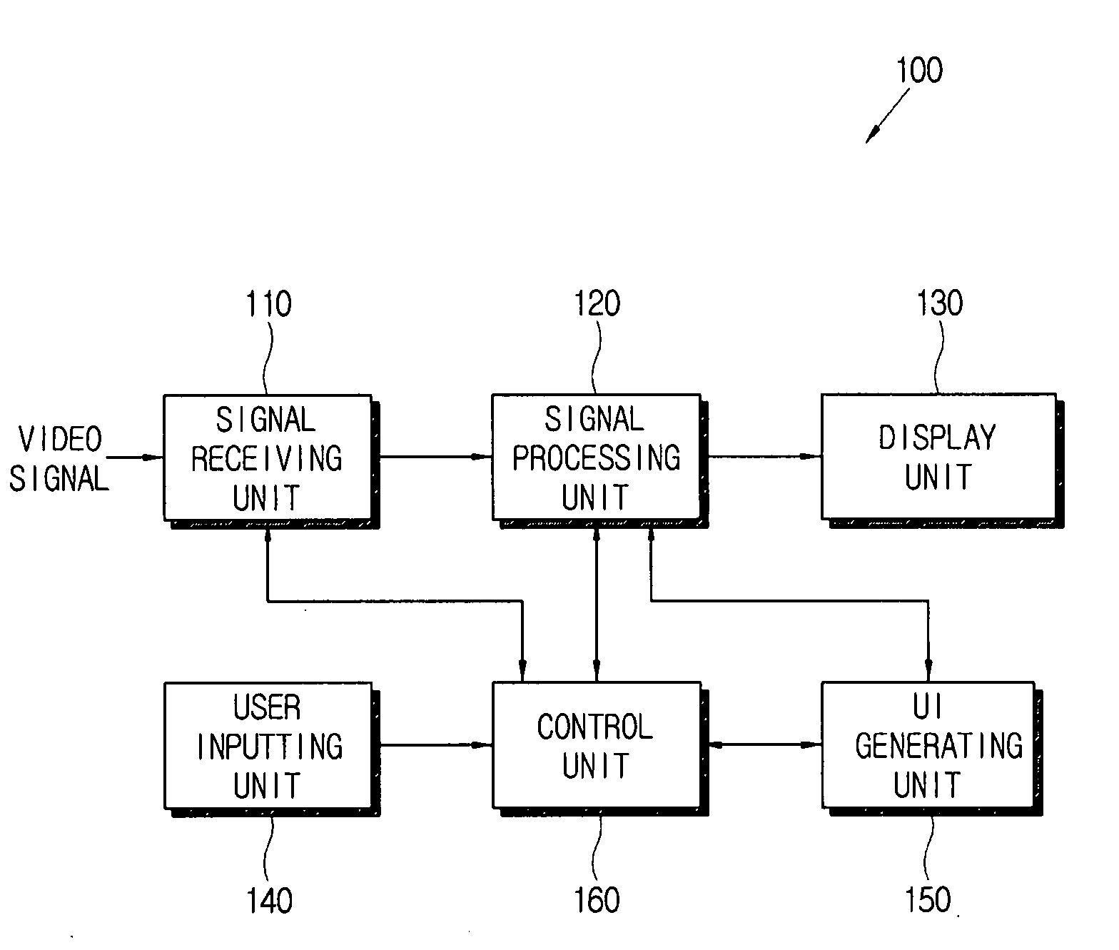
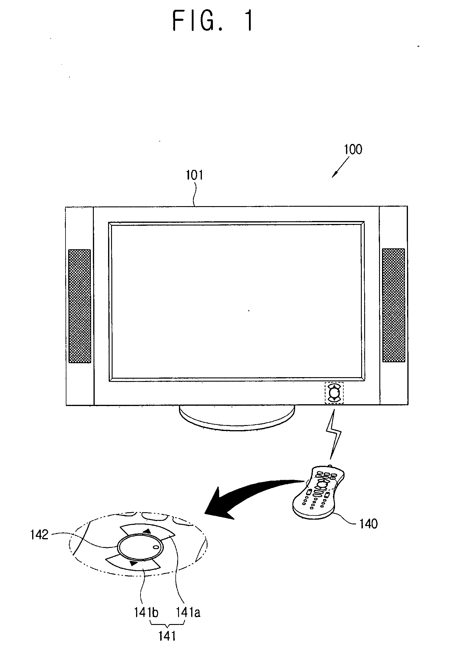
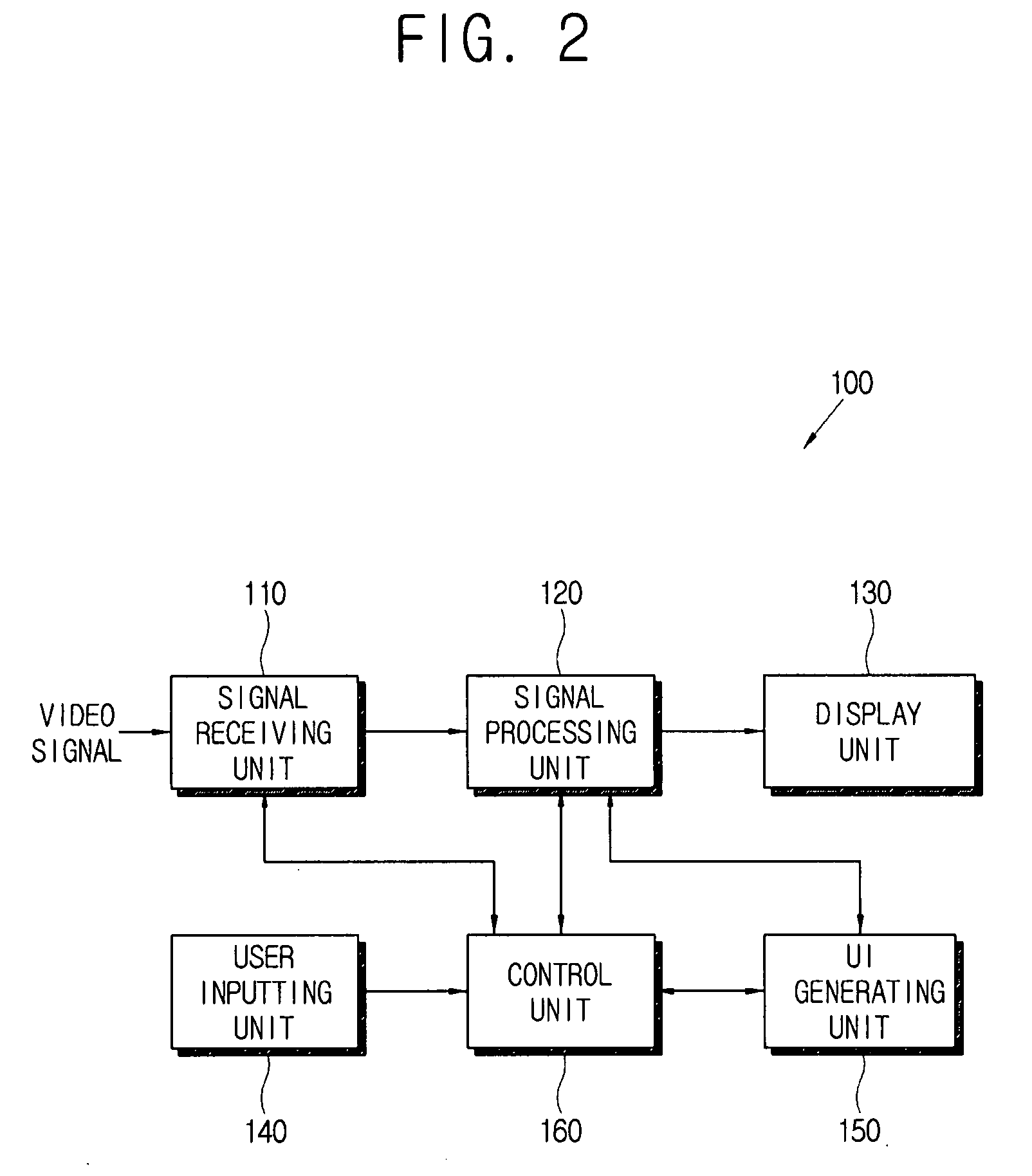
[0034]As shown in FIGS. 1 and 2, a video signal processing apparatus 100 may be provided as a TV. The video signal processing apparatus 100 includes a signal receiving unit 110, a signal processing unit 120, a display unit 130, a user inputting unit 140, a UI (user interface) generating unit 150, and a control unit 160.

[0035]The video signal processing apparatus 100 receives a video signal from a broadcasting station (not shown), processes the received video signal, and displays an image based on the processed video signal. The video signal may include a broadcasting signal provided by a TV broadcast. The video signal processing apparatus 100 rece...


PUM


Abstract

A. video. signal processing apparatus, comprises: a display unit; an user interface (UI) generating unit that generates a UI including a channel information array in which a plurality of channel informations are arranged to be displayed to the display unit; a user inputting unit that receives a first moving instruction and a second moving instruction for moving the channel information array, the second moving instruction including a position information about moving of the channel information array; and a control unit that controls the UI generating unit so that the channel informations arranged in the channel information array can move one by one if the first moving instruction is received, and the channel informations arranged in the channel information array can move in an manner that corresponds to the position information if the second moving instruction is received.

Description

CROSS-REFERENCE TO RELATED APPLICATIONS[0001]This application claims priority from Korean Patent Application No. 2006-0026253, filed on Mar. 22, 2006, in the Korean Intellectual Property Office, the disclosure of which is incorporated herein by reference.BACKGROUND OF INVENTION[0002]1. Field of Invention[0003]Methods and apparatuses consistent with the present invention relate to video signal processing, and more particularly, to video signal processing for rapidly and conveniently searching a plurality of channel informations.[0004]2. Description of the Related Art[0005]Generally, a video signal processing apparatus such as a TV, or the like receives a video signal from a broadcasting station, etc., and processes the received video signal in order to display an image based on the processed video signal. The video signal includes a broadcasting signal provided by a TV broadcast. The video signal processing apparatus receives one program from one channel among a plurality of channels...

Claims


Application Information

Patent Timeline
IPC IPC(8): G06F3/00H04N5/445
CPCH04N5/44543H04N5/44582H04N21/482H04N21/4312H04N21/4402H04N21/42222H04N21/47H04N21/42204B43M15/00Y10S411/921
Inventor KIM, YUN-SUNGKIM, GUM-SOOL
Owner SAMSUNG ELECTRONICS CO LTD
Learn More