Outer Belt Molding

a technology for outer belts and doors, applied in the direction of windows, wing accessories, transportation and packaging, etc., can solve the problems of increasing manufacturing costs, adding to the weight of the door, and aesthetically pleasing outer belts

Inactive Publication Date: 2007-10-04
MAGNA INTERNATIONAL INC
View PDF9 Cites 18 Cited by
  • Summary
  • Abstract
  • Description
  • Claims
  • Application Information

AI Technical Summary

Problems solved by technology

The above-described outer belt molding arrangements tend to be too tall and/or wide resulting in a larger outer belt molding that is not aesthetically pleasing.
Moreover,

Method used


Image

  • Outer Belt Molding
  • Outer Belt Molding
  • Outer Belt Molding

Examples


Embodiment Construction

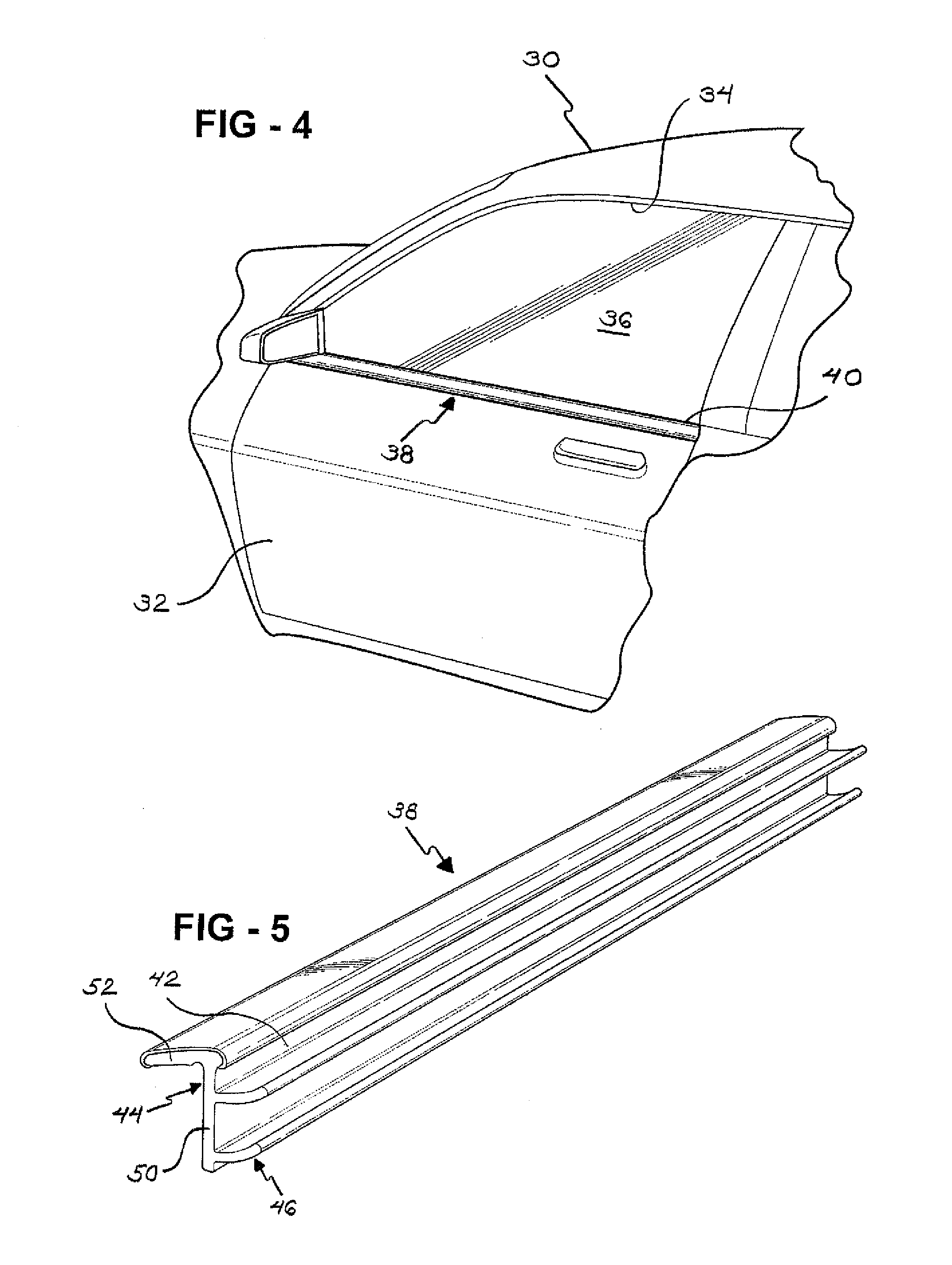
[0020]Starting with reference to FIG. 4, a motor vehicle 30 includes a door 32 defining a window opening 34. The window opening 34 is closed by a movable window pane 36. An outer belt molding, generally shown at 38, is adapted to be attached to the door 32 along a lower edge 40 of the window opening 34. The outer belt molding 38 provides a sealing engagement between the door 32 and the window pane 36 to prevent moisture from passing through the window opening 34.

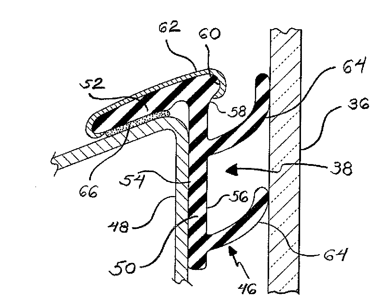
[0021]Referring to FIG. 5, the outer belt molding 38 includes an elongated main body 42 adapted to extend along the lower edge 40 of the window opening 34. The main body 42 may be formed from polypropylene or TPO. It is, however, appreciated that the main body 42 may be formed from any of numerous moldable materials. The main body 42 includes a mounting portion 44 and a sealing portion 46.

[0022]Referring to FIG. 6, the mounting portion 44 abuts a door panel 48 of the door 32. The mounting portion 44 includes a generally vert...


PUM


Abstract

An outer belt molding is provided for a motor vehicle door having a door panel defining a window opening. The outer belt molding includes an elongated main body adapted to be attached to the door panel along a lower edge of the window opening. The elongated main body includes a mounting portion including a vertical segment abutting a portion of the door panel and an outer segment extending out from the vertical segment abutting another portion of the door panel. The outer belt molding also includes fastening means extending between at least one of the outer and vertical segments and the door panel to fixedly secure the outer belt molding to the door panel.

Description

CROSS-REFERENCE TO RELATED APPLICATION[0001]This application claims the benefit of U.S. Provisional Application Ser. No. 60 / 788,831, filed Apr. 3, 2006 and entitled “Outer Belt Molding.”BACKGROUND OF THE INVENTION[0002]1. Field of the Invention[0003]The invention relates to an outer belt molding for a motor vehicle door. More particularly, the invention relates to a low profile outer belt molding for attachment to a door panel of a motor vehicle door.[0004]2. Description of Related Art[0005]Outer belt moldings are commonly secured along a flange that is formed along a door panel of a vehicle door. Three examples of conventional outer belt moldings are shown in FIGS. 1 through 3. In FIGS. 1 and 2, an outer belt molding 10 includes spaced apart legs 12, 14 defining a channel 16 for receiving a flange 18. One of the legs 12, 14 includes at least one retention gripper 20 for maintaining the outer belt molding 10 along the flange 18. In FIG. 3, the flange 18 is defines a door channel 22 ...

Claims


Application Information

Patent Timeline
IPC IPC(8): B60J1/16
CPCB60J10/041B60J10/008B60J10/36B60J10/75
Inventor KAWASE, HARUHISAELLIS, PETER J.
Owner MAGNA INTERNATIONAL INC
Why Eureka
Try Eureka