Fluid mixer utilizing viscous drag

a technology of viscous drag and mixer, which is applied in the direction of mixing, rotary stirring mixer, transportation and packaging, etc., can solve the problems of dangerous situations in high shear regions, significant energy consumption, and destruction of delicate products or reagents, and achieve good mixing effects

Inactive Publication Date: 2006-10-17
COMMONWEALTH SCI & IND RES ORG
View PDF17 Cites 45 Cited by
  • Summary
  • Abstract
  • Description
  • Claims
  • Application Information

AI Technical Summary

Benefits of technology

[0020]In operation the duct is maintained in a stationary mode and has a number of windows cut into its wall. The sleeve is mechanically moved with respect to the duct. The materials to be mixed or dispersed are fed into one end of the duct and pumped through it as the outer sleeve is moved with respect to the duct. The viscous drag from the outer sleeve, which acts on the fluid in the region of each window, sets up a secondary (tranverse) flow in the fluid. The non-window parts of the duct isolate the flow from the viscous drag of the outer sleeve in all regions except the windows. This ensures that the flow does not move simply as a solid body and ensures that the transverse flow within each window region is not axi-symmetric. Thus, as the flow passes from the influence of one window to the influence of the next, the flow experiences different shearing and stretching orientations. It is this programmed sequence of flow reorientation and stretchin that causes good mixing.

Problems solved by technology

On the other hand, stirred tank mixers can suffer from large stagnant regions and if viscous fluids are involved, consumption of energy can be significant.
The regions of high shear may destroy delicate products or reagents, for example, the biological reagents involved in viscous fermentations.
Similarly, regions of high shear may produce dangerous situations when mixing small prills of explosives in a delicate but viscous fuel gel.
Regions of high shear may also disrupt the formation and growth of particles or aggregates in a crystalliser.

Method used


Image

  • Fluid mixer utilizing viscous drag
  • Fluid mixer utilizing viscous drag
  • Fluid mixer utilizing viscous drag

Examples


Embodiment Construction

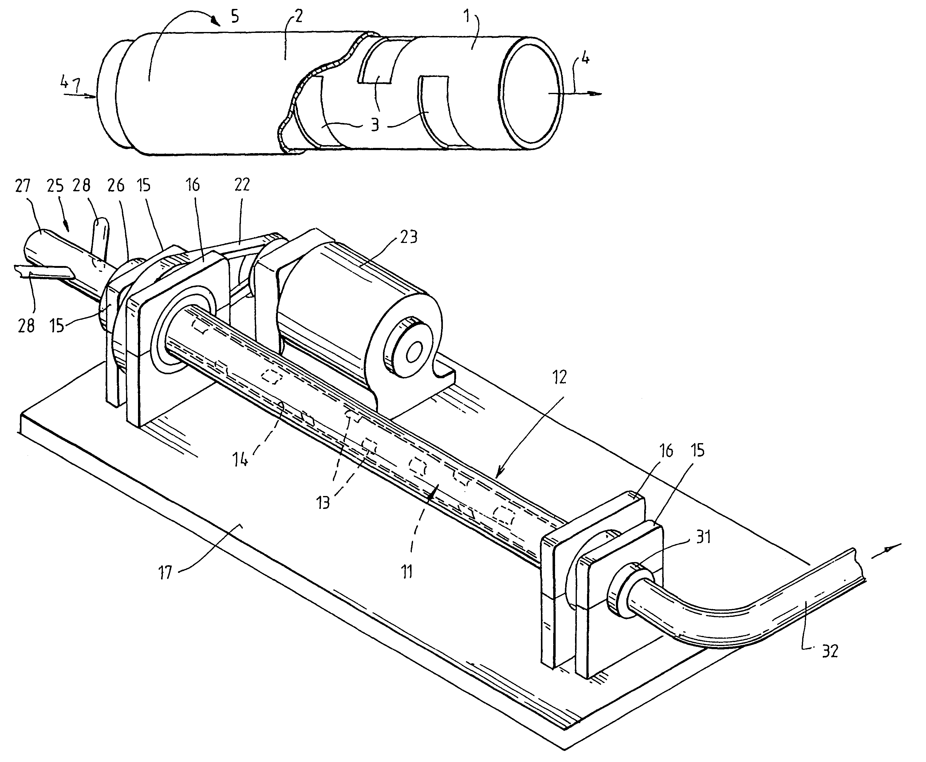
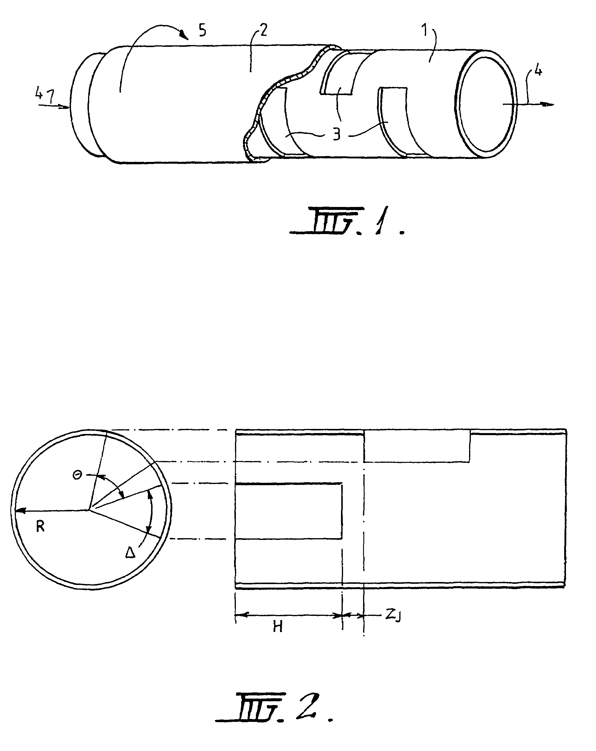
[0034]FIG. 1 depicts a stationary inner cylinder 1 surrounded by an outer rotatable cylinder 2. The inner cylinder 1 has windows 3 cut into its wall. Fluids to be mixed are passed through the inner cylinder 1 in the direction of arrow 4 and the rotatable outer cylinder 2 is rotated in the direction indicated by the arrow 5. For convenience, rotation in an anticlockwise direction is accorded a positive angular velocity and rotation in a clockwise direction is accorded a negative angular velocity in subsequent description.

[0035]As shown in FIG. 2, the geometric design parameters of the mixer are as follows:

[0036](i) R—The nominal radius of the RAM (meters) is the inner radius of the conduit

[0037](ii) Δ—The angular opening of each window (radians)

[0038](iii) Θ—The angular offset between subsequent windows (angle from the start of one window to the start of the subsequent window, radians)

[0039](iv) H—The axial extent of each window (meters)

[0040](v) ZJ—The axial window gap, or distance ...


PUM


Abstract

A fluid mixer including an inner fluid flow (11) duct having a cylindrical wall (14) provided with the window openings (13) and an outer tubular sleeve (12) disposed outside and extending along the duct (11) to cover the openings (13). Fluids to be mixed are admitted to one end of duct (11) through an inlet (25) and the mixture flows out through outlet (32). Duct (11) is statically mounted in pedestals (15) fixed to a base platform (17). Sleeve (12) is mounted for rotation in further pedestals (16) and driven by motor (23) and drive belt (22) to rotate concentrically about duct (11) such that parts of the sleeve move across the window openings (13) to create viscous drag on fluid flowing through the duct and transverse flows of fluid in the regions of the openings to promote mixing.

Description

[0001]This is a National Stage entry of application Ser. No. PCT / AU01 / 01127 filed Sep. 7, 2001, of which the claim for priority was based on provisional application 60 / 231,358 filed Sep. 8, 2000; the disclosure of which is incorporated herein by reference.TECHNICAL FIELD[0002]The present invention relates to fluid mixers and more generally to techniques for mixing materials within fluids.[0003]Typical static mixers are characterised by baffles, plates and constrictions that result in regions of high shear and material build-up. On the other hand, stirred tank mixers can suffer from large stagnant regions and if viscous fluids are involved, consumption of energy can be significant. Stirred tank mixers are also normally characterised by regions of high shear.[0004]The regions of high shear may destroy delicate products or reagents, for example, the biological reagents involved in viscous fermentations. Similarly, regions of high shear may produce dangerous situations when mixing small...

Claims


Application Information

Patent Timeline
Patent Type & Authority Patents(United States)
IPC IPC(8): B01F5/06B01F9/02B01F29/60
CPCB01F7/008B01F27/272
Inventor PARKER METCALFE, III, GUYRUDMAN, MURRAY
Owner COMMONWEALTH SCI & IND RES ORG
Why Eureka
Try Eureka