
Rendering apparatus, method and program, and shape data generation apparatus, method and program

a technology of image rendering and shape data, applied in the field of image rendering shape data generation apparatus, method and program, can solve the problems of aliasing, reducing rendering efficiency, and requiring too many triangular polygons

Inactive Publication Date: 2007-10-04
KK TOSHIBA
View PDF14 Cites 34 Cited by
  • Summary
  • Abstract
  • Description
  • Claims
  • Application Information

AI Technical Summary

Benefits of technology

[0009] In accordance with a first aspect of the invention, there is provided a rendering apparatus comprising: a shape data input unit configured to input vector graphics data; a feature quantity computation unit configured to compute a shape feature quantity related to the vector graphics data, the shape feature quantity indicating complexity of a shape represented by the vector graphics data, or indicating complexity of a character represented by the shape of the vector graphics data; an acquisition unit configured to acquire, as a plurality of rendering parameters, a position of the shape on a screen, and a matrix indicating affine transformation to the position; a pixel number computation unit configured to compute number of pixels which are included in a rendering region of the shape, based on the rendering parameters; a first conversion unit configured to convert the vector graphics data into bitmap texture data when the number of pixels is smaller than the shape feature quantity; a first rendering unit configured to render the bitmap texture data; a second conversion unit configured to convert the vector graphics data into polygon model data attached with a curve-parameter when the number of pixels fails to be smaller than the shape feature quantity; a second rendering unit configured to render the polygon model data; a selection unit configured to select one of the first conversion unit and the second conversion unit and one of the first rendering unit and the second rendering unit according to the input vector graphics data by comparing the number of pixels with the shape feature quantity; and a presentation unit configured to present a selected one of the rendered bitmap texture data and the rendered polygon model data.

Problems solved by technology

If all characters displayed on the screen are rendered using this method, it is necessary to render too many triangular polygons.
This inevitably reduces the rendering efficiency.
Further, when a reduced image of a character of a large stroke count is displayed, the linear lines of a plurality of triangular polygons are rendered in each pixel, with the result that aliasing occurs and a character hard to make out is produced.
Similar problems may well occur in the case of general graphics object, too.

Method used


Image

  • Rendering apparatus, method and program, and shape data generation apparatus, method and program
  • Rendering apparatus, method and program, and shape data generation apparatus, method and program
  • Rendering apparatus, method and program, and shape data generation apparatus, method and program

Examples


first embodiment

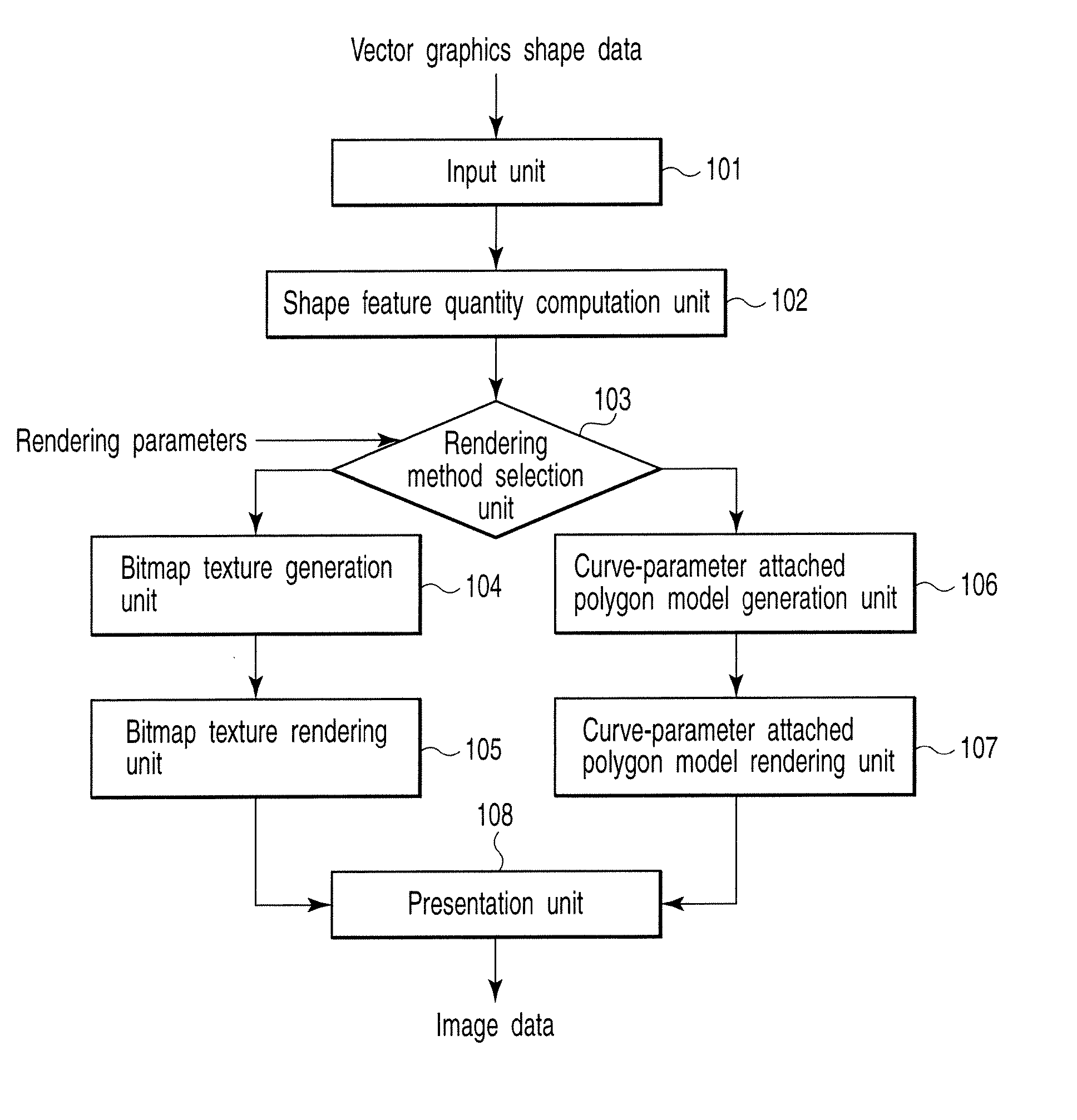
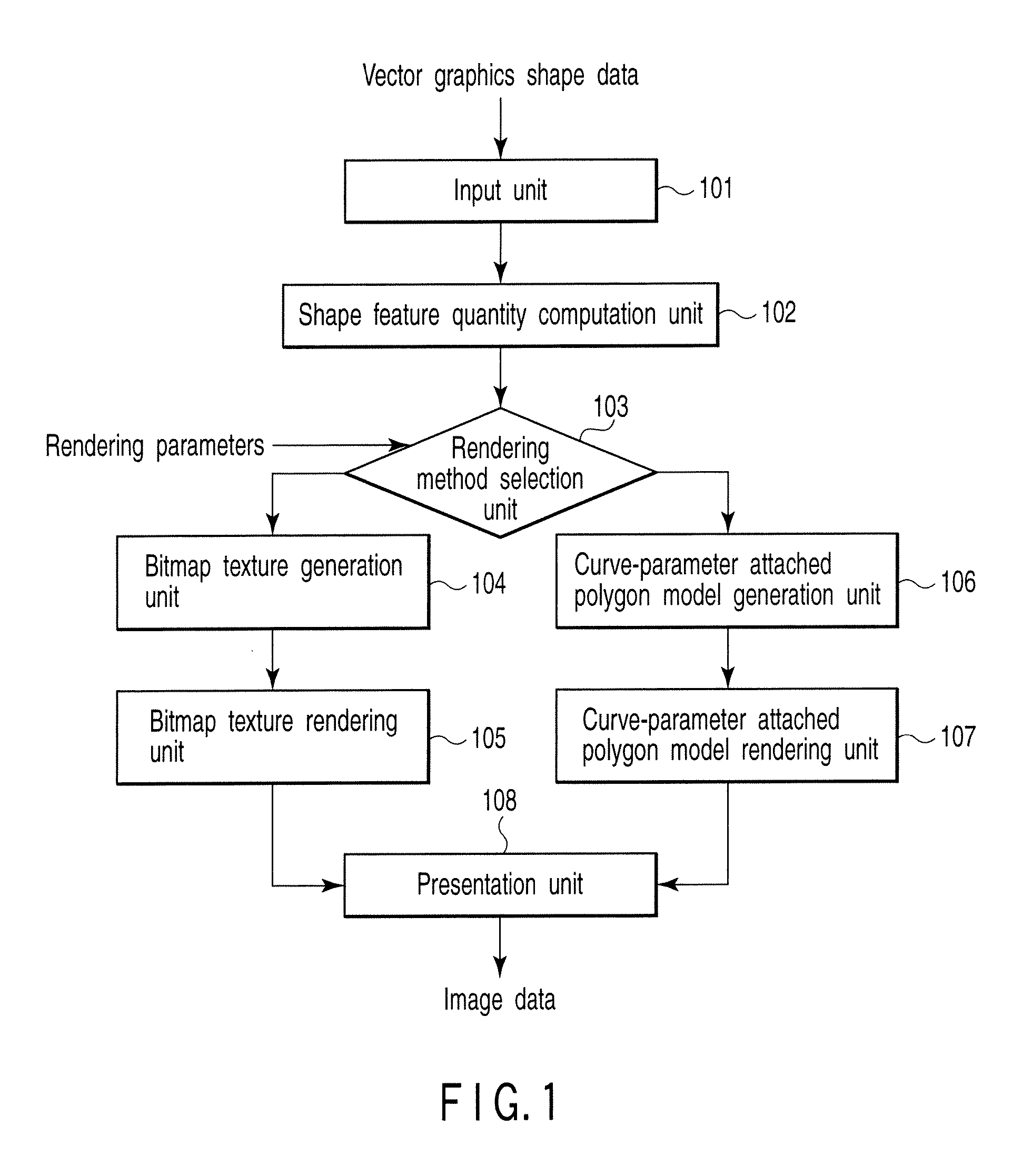
[0040] Referring to FIG. 1, a rendering apparatus according to a first embodiment of the invention will be described. FIG. 1 is a view useful in explaining the configuration of the rendering apparatus of the first embodiment. This apparatus obtains vector graphics shape data and rendering parameters, and outputs image data as the result of vector graphics rendering.

[0041] As shown in FIG. 1, the rendering apparatus of the first embodiment comprises an input unit 101, shape feature quantity computation unit 102, rendering method selection unit 103, bitmap texture generation unit 104, bitmap texture rendering unit 105, curve-parameter attached polygon model generation unit 106, curve-parameter attached polygon model rendering unit 107 and presentation unit 108.

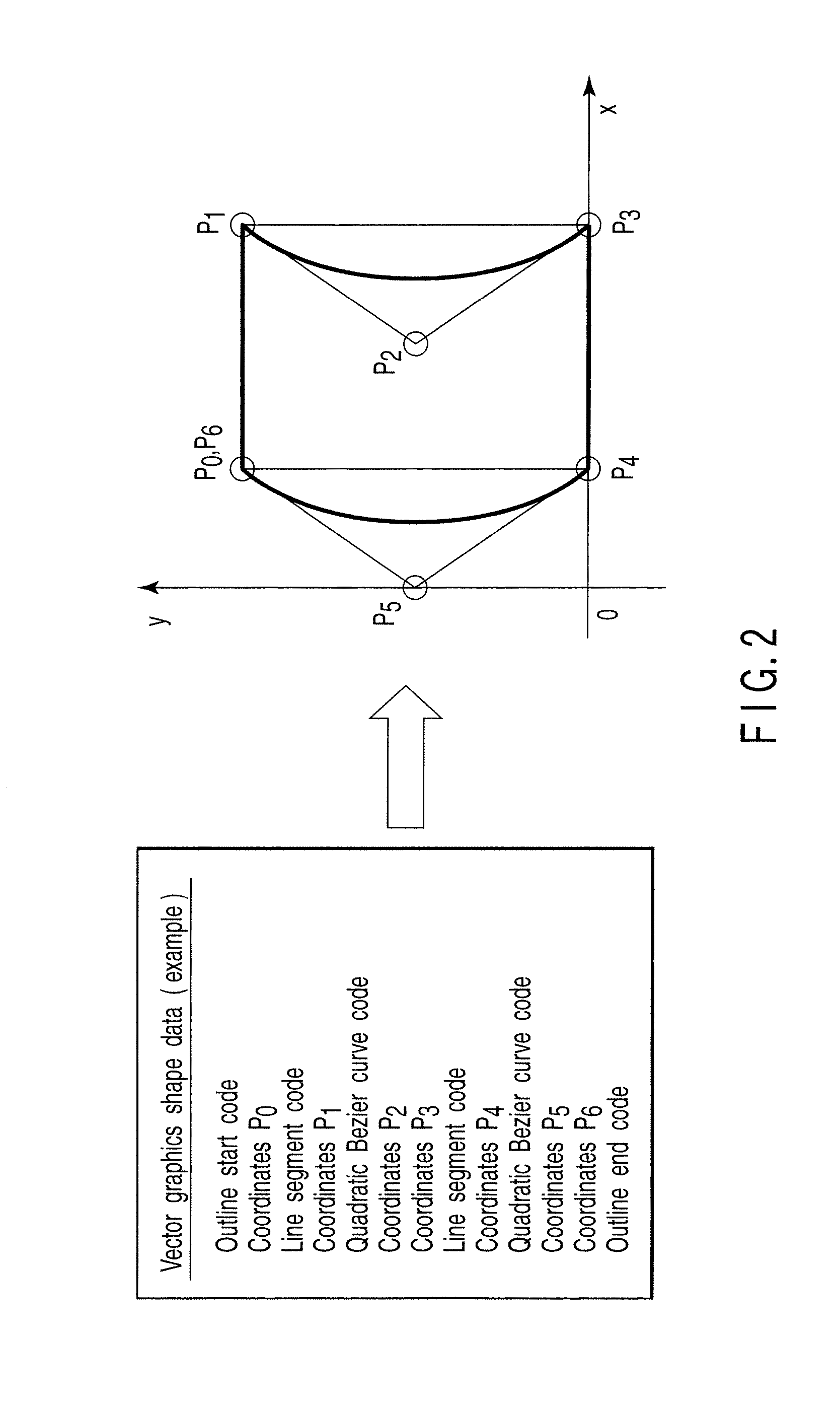
[0042] The input unit 101 permits vector graphics shape data to be input. The vector graphics shape data will be described later with reference to FIG. 2.

[0043] The shape feature quantity computation unit 102 computes the sha...

second embodiment

[0078] An image rendering apparatus according to a second embodiment comprises a shape data generation apparatus and image data output apparatus separate therefrom. The shape data generation apparatus receives vector graphics shape data, and outputs structured vector graphics shape data before rendering the vector graphics shape data. The image data output apparatus receives the output structured vector graphics shape data and rendering parameters, and outputs image data as a result of vector graphics shape rendering.

[0079] Referring to FIGS. 10, 11 and 12, the shape data generation apparatus employed in the second embodiment will be described.

[0080] The shape data generation apparatus comprises an input unit 101, shape feature quantity computation unit 102, bitmap texture generation unit 104, curve-parameter attached polygon model generation unit 106 and output unit 1001. In the description below, elements similar to the above-described ones are denoted by corresponding reference...

third embodiment

[0088] Referring to FIG. 14, a rendering apparatus according to a third embodiment will be described. The third embodiment is directed to, for example, an apparatus that receives a text character string, and outputs image data indicating the results of rendering of outline fonts corresponding to the text character string.

[0089] The rendering apparatus of the third embodiment comprises an input unit 1401, outline font database 1402, vector graphics shape generation unit 1403, shape feature quantity computation unit 102, rendering method selection unit 103, bitmap texture generation unit 104, bitmap texture rendering unit 105, curve-parameter attached polygon model generation unit 106, curve-parameter attached polygon model rendering unit 107 and presentation unit 108.

[0090] The input unit 1401 receives a text character string, and transfers the characters, included in the string, to the vector graphics shape generation unit 1403 one by one.

[0091] The outline font database 1402 out...


PUM


Abstract

Rendering apparatus includes input unit inputting vector graphics data, computation unit computing shape feature quantity related to vector graphics data, acquisition unit acquiring, as rendering parameters, position of shape on screen, and matrix indicating affine transformation to position, computation unit computing number of pixels, first conversion unit converting vector graphics data into bitmap texture data when number of pixels is smaller than shape feature quantity, first rendering unit rendering bitmap texture data, second conversion unit converting vector graphics data into polygon model data attached with a curve-parameter when the number of pixels fails to be smaller than shape feature quantity, second rendering unit rendering polygon model data, selection unit selecting one of first and second conversion units and one of first and second rendering units by comparing number of pixels with shape feature quantity, and presentation unit presenting selected one of rendered bitmap texture data and rendered polygon model data.

Description

CROSS-REFERENCE TO RELATED APPLICATIONS [0001] This application is based upon and claims the benefit of priority from prior Japanese Patent Application No. 2006-094358, filed Mar. 30, 2006, the entire contents of which are incorporated herein by reference. BACKGROUND OF THE INVENTION [0002] 1. Field of the Invention [0003] The present invention relates to an image rendering apparatus, method and program, and a shape data generation apparatus, method and program. [0004] 2. Description of the Related Art [0005] In accordance with the progress of high definition (HD), it is considered that the necessity of techniques for efficiently rendering high-quality vector graphics data or outline font object in a Computer Graphics (CG) image of high definition will be increased. [0006] A method for efficiently rendering vector graphics object using a graphics processing unit (GPU) as a graphics LSI has been published by, for example, C. Loop and J. Blinn, “Resolution Independent Curve Rendering ...

Claims


Application Information

Patent Timeline
Patent Type & Authority Applications(United States)
IPC IPC(8): G06T11/20G06T11/00
CPCG06T11/203G06T15/00G06T7/00
Inventor SUGITA, KAORUMIHARA, ISAO
Owner KK TOSHIBA
Learn More