Vented and ducted sub-rack support member

Active Publication Date: 2007-10-04
NATIONAL INSTRUMENTS
View PDF33 Cites 15 Cited by
  • Summary
  • Abstract
  • Description
  • Claims
  • Application Information

AI Technical Summary

Benefits of technology

[0009] A chassis for plug-in modules may be provided with a vented and ducted sub-rack support member. The vented and ducted sub-rack support member may deflect a portion of the air flowing within the chassis through vents in the top surface of the vented and ducted sub-rack support member in order to increase the air flow to heat producing components mounted on or near the backplane above the support member. The increased air flow may increase air flow velocity a

Problems solved by technology

However, due to the compact design of these modules, parts of the module may be difficult to cool sufficiently.
However, the air flow depicted in FIG. 1B may be ineffective in providing sufficient cooling to heat producin

Method used


Image

  • Vented and ducted sub-rack support member
  • Vented and ducted sub-rack support member
  • Vented and ducted sub-rack support member

Examples


Example

[0032] While the invention is susceptible to various modifications and alternative forms, specific embodiments thereof are shown by way of example in the drawings and are herein described in detail. It should be understood, however, that the drawings and detailed description thereto are not intended to limit the invention to the particular form disclosed, but on the contrary, the intention is to cover all modifications, equivalents and alternatives falling within the spirit and scope of the present invention as described by the appended claims. As used herein, the term “connected” means “directly or indirectly connected”, and the term “coupled” means “directly or indirectly connected”.

DETAILED DESCRIPTION OF THE INVENTION

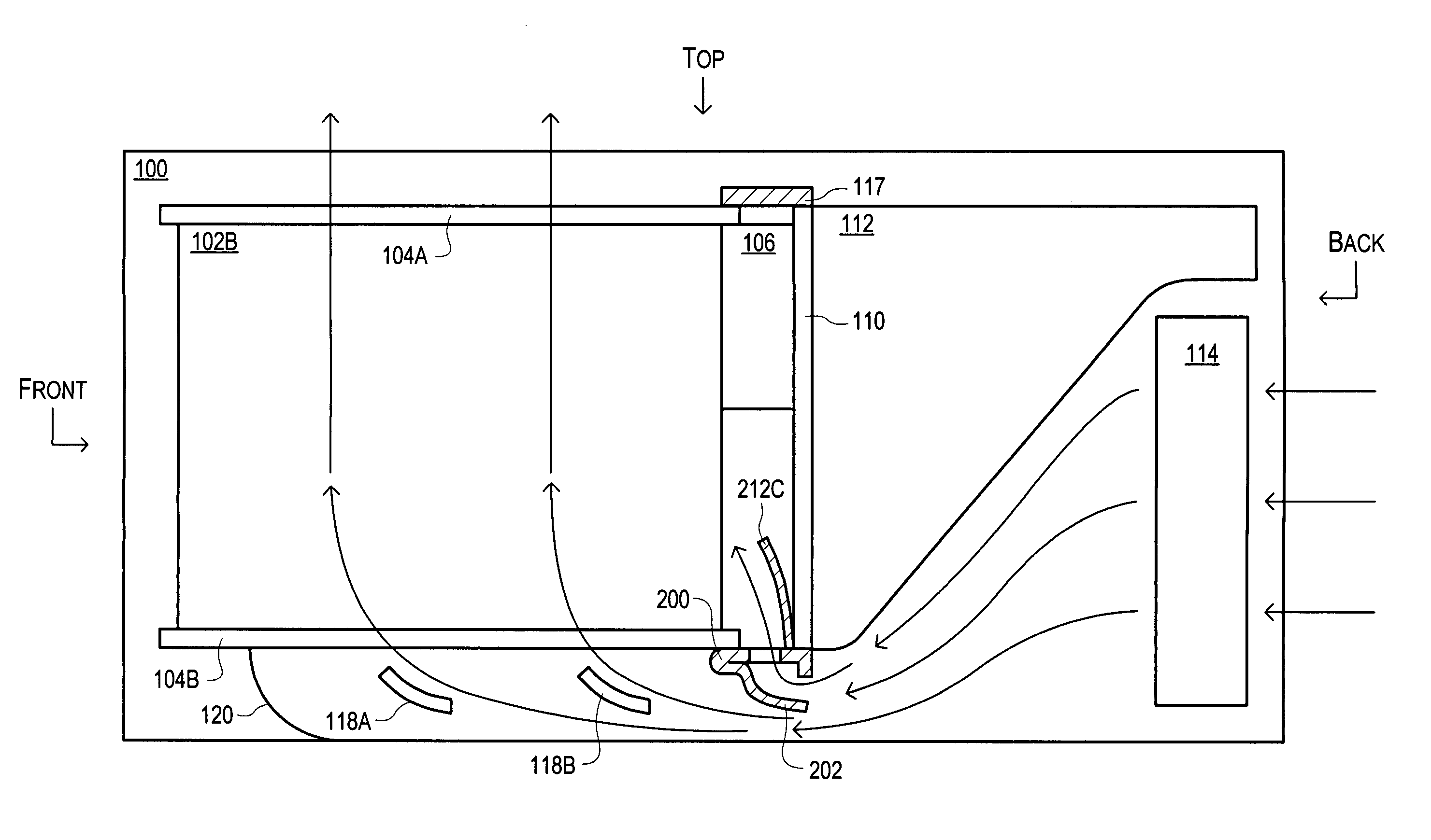
[0033] Vented and Ducted Sub-rack Support Member

[0034]FIG. 2 illustrates one set of embodiments of an internal structure of a chassis 100 designed to receive plug-in modules, such as plug-in module 102B. The plug-in module 102B may be guided during insertion into...


PUM


Abstract

A chassis for plug-in modules may be provided with a vented and ducted sub-rack support member. The vented and ducted sub-rack support member may deflect a portion of the air flowing within the chassis through vents in the top surface of the vented and ducted sub-rack support member in order to increase the air flow to heat producing components mounted on the backplane above the support member. The increased air flow may increase air flow velocity and decrease the ambient temperature of the air around these components and improve the dissipation of heat from each component into the air. Air flow above the vented and ducted sub-rack support member may also be redirected by upper deflectors mounted on the support member to portions of plug-in cards adjacent to the upper deflectors and may provide additional cooling to components on the plug-in cards near the backplane.

Description

BACKGROUND OF THE INVENTION [0001] 1. Field of the Invention [0002] The present invention relates generally to mechanisms for cooling heat producing components on electronic circuit boards, and more particularly, to the cooling of components by air flow generated by fans. [0003] 2. Description of the Related Art [0004] Instruments for collecting data or information from an environment or unit under test may be coupled to and controlled by computer systems. Data collected by these instruments may be used to control units being tested (e.g., an overheated unit may be shutdown) or an environment (e.g., ventilation systems may be activated if a certain chemical is detected in the air). Data may also be displayed to a user for control and / or experimental purposes (e.g., to improve the design of the unit being tested). Instruments and / or computer systems may also perform various data analysis and data processing on acquired data prior to control of the unit and / or display of the data to t...

Claims


Application Information

Patent Timeline
IPC IPC(8): H05K7/20
CPCH05K7/20563
Inventor BALDWIN, RICHARD G. JR.
Owner NATIONAL INSTRUMENTS
Why Eureka
Try Eureka