Joint connector

Active Publication Date: 2020-09-24
SUMITOMO WIRING SYST LTD
View PDF0 Cites 1 Cited by
  • Summary
  • Abstract
  • Description
  • Claims
  • Application Information

AI Technical Summary

Benefits of technology

The invention is a heat dissipation plate for a busbar terminal. The plate is designed to improve heat transfer from the busbar terminal to the plate, ensuring better heat dissipation. The plate has a side surface corresponding portion that matches the holding portion of the busbar terminal, allowing for easy transfer of heat from the holding portion to the side surface of the plate. Additionally, the plate has a groove on its surface that allows for additional heat transfer to the bottom surface of the groove, further improving heat dissipation. Overall, this design improves heat dissipation efficiency and prevents overheating of the busbar terminal.

Problems solved by technology

Heat from the holding portion easily is transferred to the side surfaces of the housing, and the side surfaces tend to get hot.

Method used


Image

  • Joint connector
  • Joint connector
  • Joint connector

Examples


Embodiment Construction

[0015]A specific example of a joint connector 10 of this disclosure is described below with reference to the drawings. Note that the present disclosure is not limited to these illustrations and is intended to be represented by claims and include all changes in the scope of claims and in the meaning and scope of equivalents.

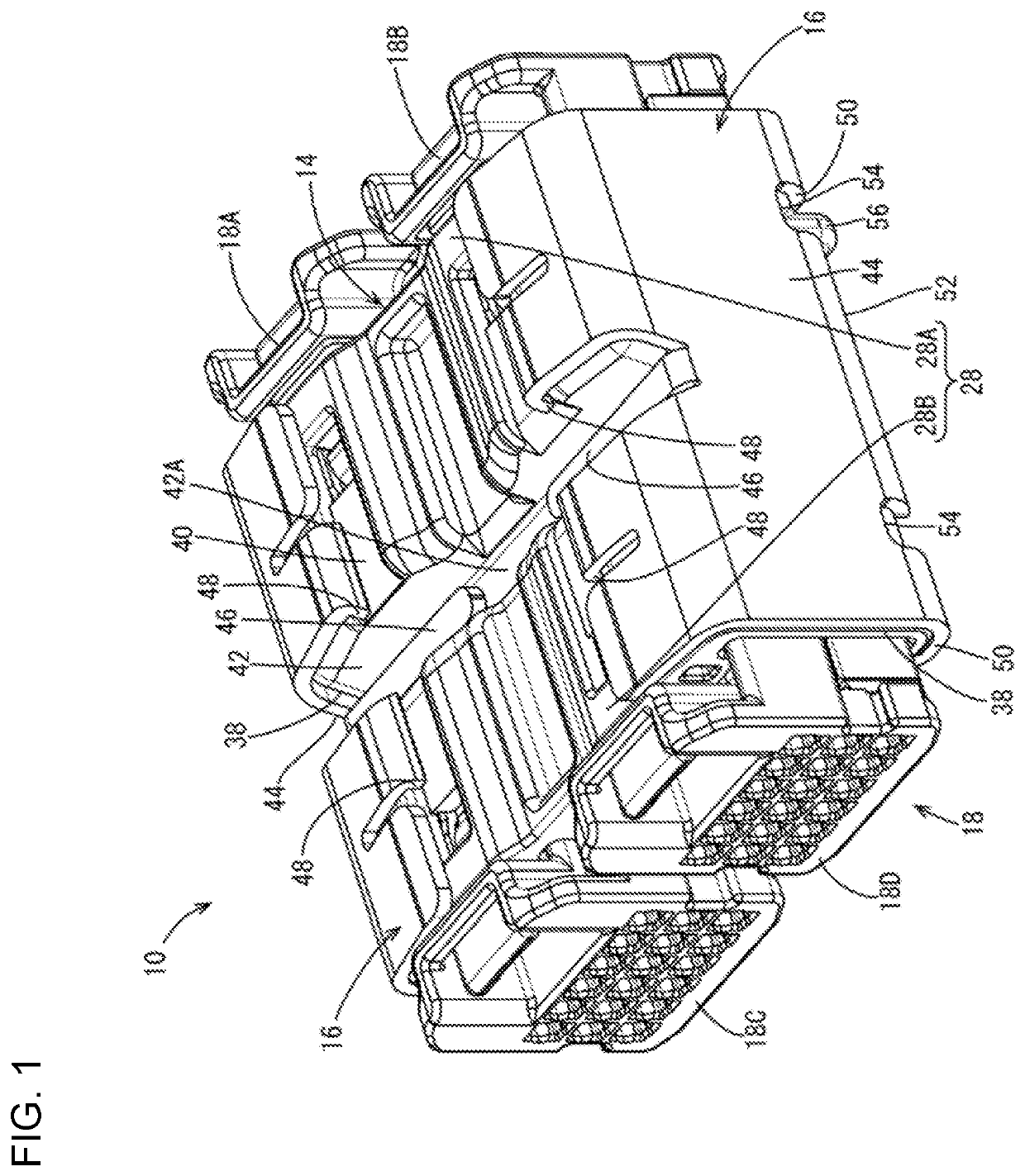
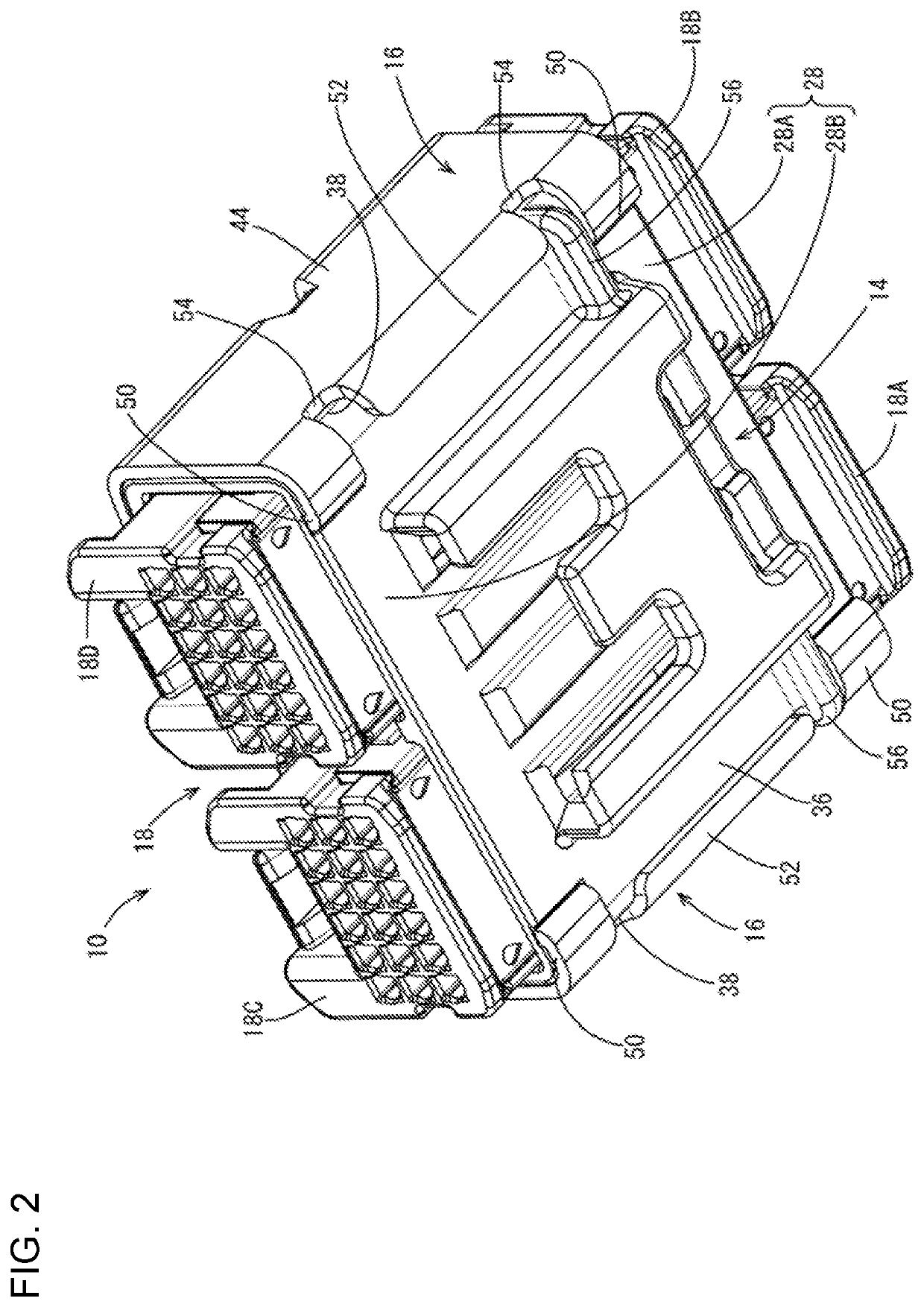
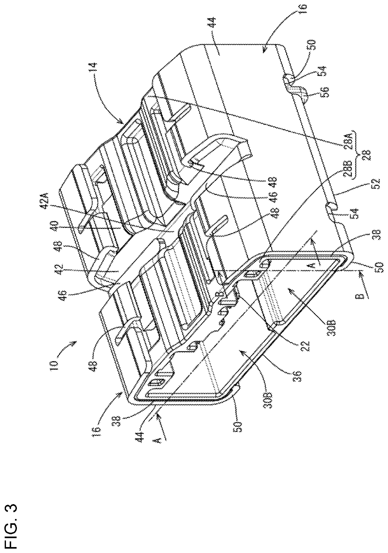
[0016]As shown in FIGS. 4 and 5, the joint connector 10 of this embodiment includes busbar terminals 12, a housing 14 and heat dissipation plates 16. As shown in FIGS. 1 and 2, four mating connectors 18 (mating connectors 18A, 18B, 18C and 18D) are connected to the joint connector 10. In the following description, a front-rear direction is based on a connecting direction of the housing 14 and the mating connectors 18. Further, a direction from a side surface 38 on a back side toward a side surface 38 on a front side in FIG. 3 is a rightward direction along a lateral direction. Further, a direction from a lower side toward an upper side in FIG. 3 is an upward direc...


PUM


Abstract

It is aimed to improve heat dissipation. A joint connector (10) includes busbar terminals (12), a housing (14) and heat dissipation plates (16). The housing (14) includes at least two fittings (30) and a holding portion (32) defining the two fitting portions (30) and holding the busbar terminals (12). The heat dissipation plates (16) are mounted to contact outer surfaces close to the holding portion (32).

Description

BACKGROUNDField of the Invention[0001]This disclosure relates to a joint connector.Related Art[0002]Japanese Unexamined Patent Publication No. 2004-111279 discloses a joint connector with a male connector including male terminals and a female connector including female terminals to be fit to the male terminals. The male terminals are at predetermined intervals in one direction and a direction intersecting the one direction on a printed circuit board. The male terminals are connected selectively by a copper foil circuit on the printed circuit board.[0003]Heat generated at terminal contact points when energizing this joint connector is transferred to the circuit board via the male terminals and is dissipated to outside from the circuit board. However, heat easily accumulates in a housing and heat dissipation is reduced, for example, if busbar terminals are press-fit and held in a separation wall in the housing.SUMMARY[0004]This disclosure is directed to a joint connector with busbar t...

Claims


Application Information

Patent Timeline
IPC IPC(8): H01R13/518
CPCH01R13/518H01R13/502H01R12/716H05K7/20418H01R31/08
Inventor TAKAGI, KOHEI
Owner SUMITOMO WIRING SYST LTD
Why Eureka
Try Eureka