
Semiconductor packaging structure and forming method thereof
一种封装结构、成型方法的技术,应用在半导体器件、半导体/固态器件制造、半导体/固态器件零部件等方向,能够解决集成电路引线框架散热片散热功能有限等问题,达到防止芯片的破裂、加速散热、减少作业流程的效果
- Summary
- Abstract
- Description
- Claims
- Application Information
AI Technical Summary
Problems solved by technology
Method used
Image


Examples
Embodiment 1
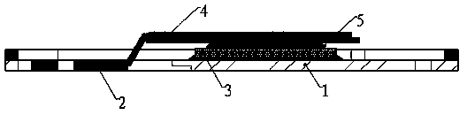
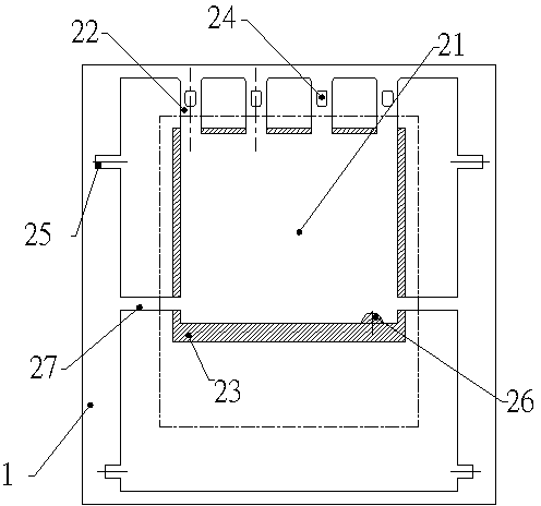
[0041] refer to Figure 1 to Figure 5 , a semiconductor packaging structure molding method, it comprises the following steps:
[0042] Prepare the lead frame 1: a semi-etched area 23 is provided around the chip holder 21 of the lead frame 1, the first pin 22 is connected to the chip holder 21, and the electrode of the chip holder 21 is directly connected to the first pin 22, and the first pin 22 is connected to the first pin 22. The pin 22 is provided with a first tin climbing hole 24, and the lead frame 1 is also provided with a positioning groove 25, a pin identification hole 26 and a first connecting rod 27;
[0043] Welding the chip 3: using the bonding material 5 to weld the chip 3 on the chip holder 21;
[0044] Prepare the heat sink frame 2: the heat sink frame 2 is provided with a back half-etched area 41 and a front half-etched area 42, and is provided with a second pin 43 and a third pin 44, and the second pin 43 and the third pin The pins 44 are all provided with ...
PUM
 Abstract
Description
Claims
Application Information