Time correction control apparatus and method of time correction control

a time correction control and time correction technology, applied in the direction of electric winding, instruments, horology, etc., can solve the problems of internal time reset or stopped, it takes six seconds or more to receive one subframe from the plurality of subframes, and the power consumption of the time correction control apparatus is also increased. , to achieve the effect of reducing power consumption

Active Publication Date: 2007-10-04
CASIO COMPUTER CO LTD
View PDF3 Cites 45 Cited by
  • Summary
  • Abstract
  • Description
  • Claims
  • Application Information

AI Technical Summary

Benefits of technology

[0011]Hence, it is a main object of the present invention to provide a time correction control apparatus and a time correction control method capable of precisely correcting time of internal time, and capable of reducing power consumption.

Problems solved by technology

According to this technique, however, it takes six seconds or more to receive one subframe from the plurality of subframes constituting the navigation data.
Thus, in order to receive all of the plurality of subframes, the receiving time is correspondingly increased and thus, the power consumption of the time correction control apparatus is also increased.
The internal time is reset or stopped in some cases due to battery exhaustion, erroneous setting of user and a program error of the time correction control apparatus.
There is also a fear that this time difference is increased to a unit of year / month / day.

Method used


Image

  • Time correction control apparatus and method of time correction control
  • Time correction control apparatus and method of time correction control
  • Time correction control apparatus and method of time correction control

Examples


first embodiment

[0030]The embodiments of the invention will be explained with reference to FIGS. 1 to 7.

[0031]First, a structure of an apparatus of the embodiment will be explained with reference to FIGS. 1, 2A, 2B and 2C.

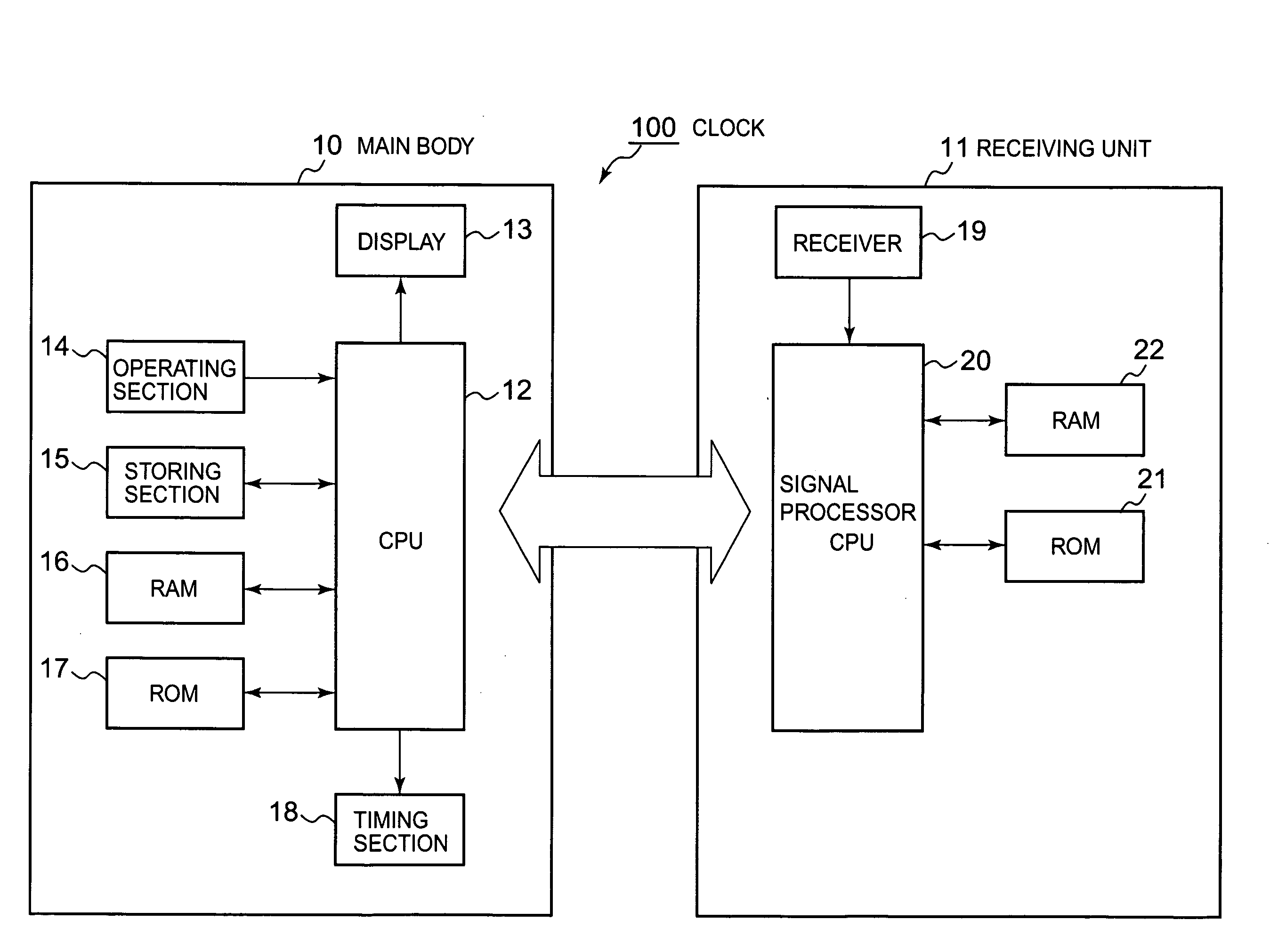
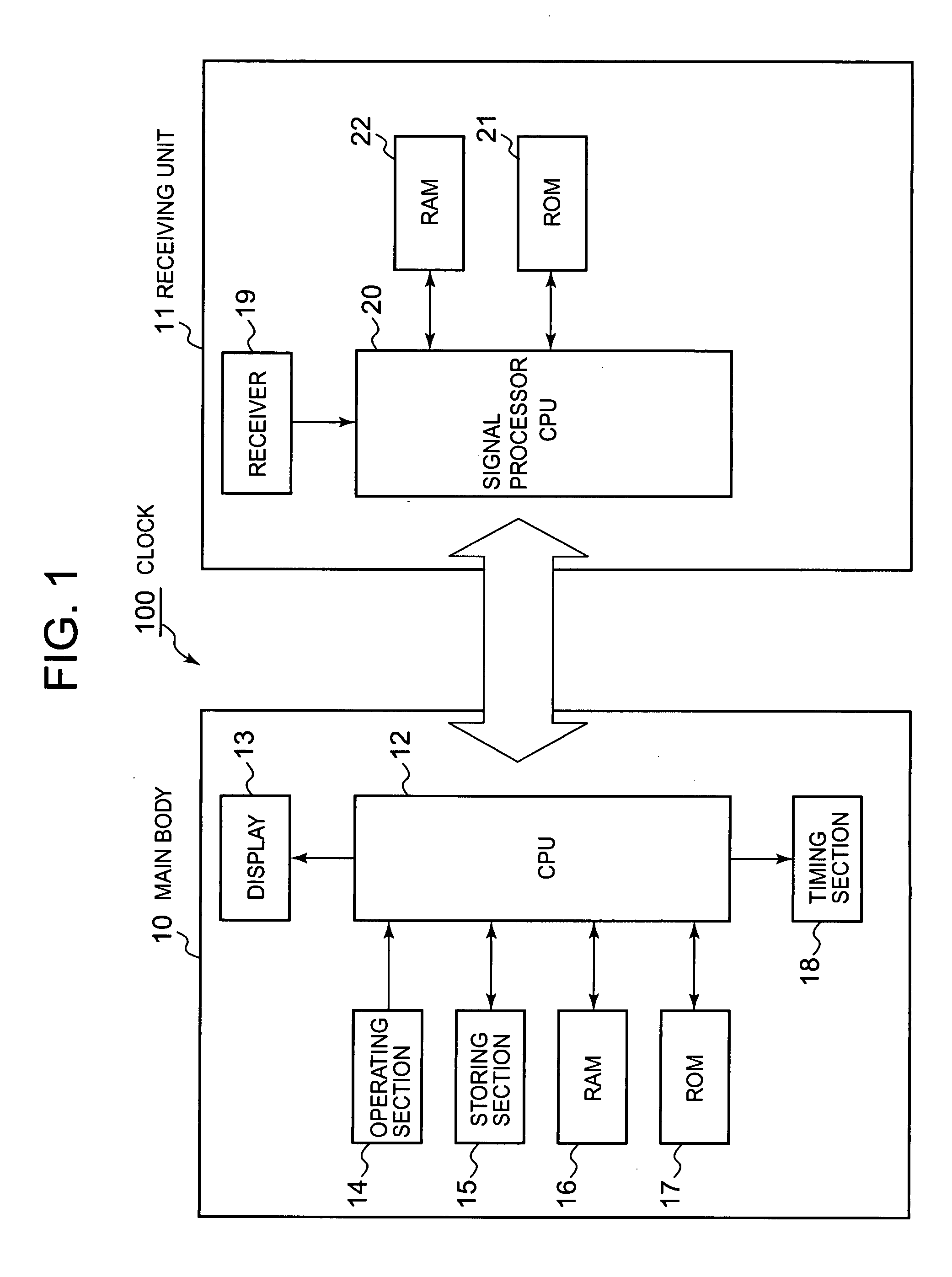
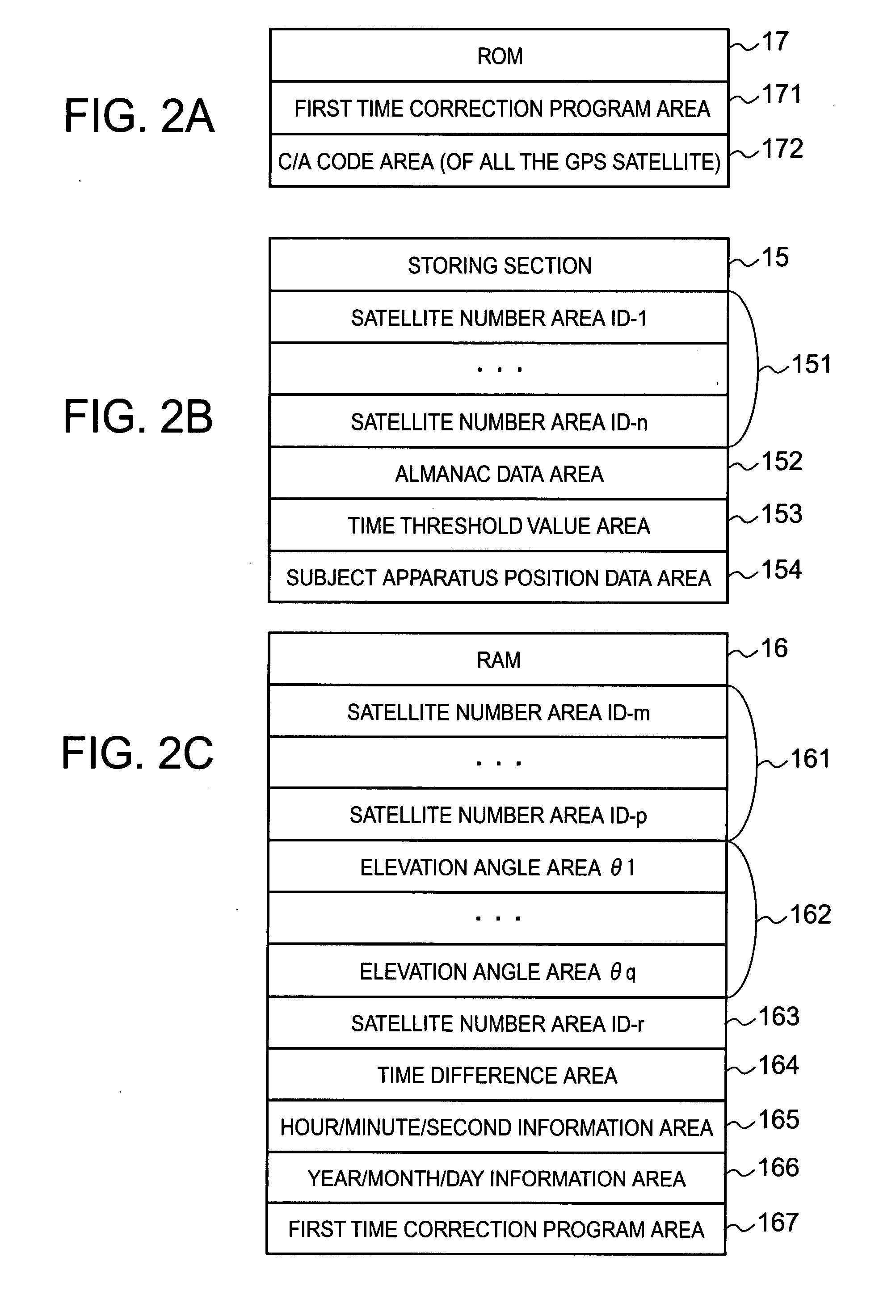
[0032]FIG. 1 shows a structure of a clock 100 of the embodiment. FIG. 2A shows a storing configuration of a ROM 17. FIG. 2B shows a storing configuration of a storing section15. FIG. 2C shows a storing configuration of a RAM 16.

[0033]As shown in FIG. 1, the clock 100 includes a main body 10 and a receiving unit 11. The main body 10 includes a CPU 12, a display 13, an operating section 14, a storing section 15, a RAM 16, a ROM 17 and a timing section 18.

[0034]The CPU 12 develops, in the RAM 16, a program designated from system programs and various application programs stored in the ROM 17, and executes various processing in cooperation with the program developed in the RAM 16. Especially, a first time correction program is stored in the ROM 17.

[0035]The CPU 12 obtains a GPS signal ...

second embodiment

[0072]A second embodiment of the present invention will be explained with reference to FIG. 7.

[0073]FIG. 7 is a flowchart of second time correction processing.

[0074]In an apparatus structure of this embodiment, the clock 100 is used like the first embodiment, and the same elements are designated with the same symbols. Detailed explanation of the same portion will be omitted and only different portions will explained.

[0075]In the clock 100, a second time correction program is stored in the ROM 17.

[0076]The second time correction processing to be executed by the clock 100 of the embodiment will be explained with reference to FIG. 7. The second time correction processing is processing for correcting year / month / day and hour / minute / second of the internal time when a subframe 1 of the navigation data of the GPS signal is received.

[0077]For example, in the clock 100, the input of the execution instructions of the second time correction processing through the operating section 14 triggers t...


PUM


Abstract

A time correction control apparatus which calculates a time difference between hour / minute / second indicated in hour / minute / second information included in a received GPS signal, and which corrects counted year / month / date and hour / minute / second by using both the received year / month / date information and hour / minute / second information when the calculated time difference is greater than the predetermined time difference, and corrects the counted hour / minute / second by using the received hour / minute / second information when the calculated time difference is smaller than the predetermined time difference.

Description

BACKGROUND OF THE INVENTION[0001]1. Field of the Invention[0002]The present invention relates to a time correction control apparatus and a method of time correction control.[0003]2. Description of the Related Art[0004]A GPS (Global Positioning System) satellite is an Earth-orbiting satellite which orbits around six orbits of inclination angle of about 55° at an altitude of 20,000 km. The number of GPS satellites has been increased due to enlargement of receiving range of a GPS receiver and reduction of regional difference in receiving state. At present, the number of GPS satellites is 28.[0005]A GPS signal is sent from the GPS satellite. Here, the GPS signal is a radio signal sent from the GPS satellite. The frequency of the GPS signal sent from the GPS satellite is basically 1575.42 MHz (name: L1 wave). A signal called commercial C / A code (Coarse / acquisition code) is added to the frequency. Here, the C / A code is a code which is encoded by PRN code (Pseudo Random Noise Code) which i...

Claims


Application Information

Patent Timeline
Patent Type & Authority Applications(United States)
IPC IPC(8): G04C11/02G04G5/00G04G21/04G04R20/00G04R20/02
CPCG01S19/14G01S19/23G04C9/02G04R20/04G04G21/04G04R20/02G04G5/002
Inventor NAKAGAWA, MAKOTO
Owner CASIO COMPUTER CO LTD
Why Eureka
Try Eureka