Method for measuring airlink transmission latency in a 1x-EVDO wireless network

a wireless network and airlink technology, applied in the field of communication, can solve the problem that packets cannot be blocked

Inactive Publication Date: 2007-10-04
LUCENT TECH INC
View PDF4 Cites 27 Cited by
  • Summary
  • Abstract
  • Description
  • Claims
  • Application Information

AI Technical Summary

Problems solved by technology

In “best efforts” 1x-EVDO wireless networks, “blocking”-type measures are unavailable, and data packets cannot be blocked based on delay.

Method used


Image

  • Method for measuring airlink transmission latency in a 1x-EVDO wireless network
  • Method for measuring airlink transmission latency in a 1x-EVDO wireless network
  • Method for measuring airlink transmission latency in a 1x-EVDO wireless network

Examples


Embodiment Construction

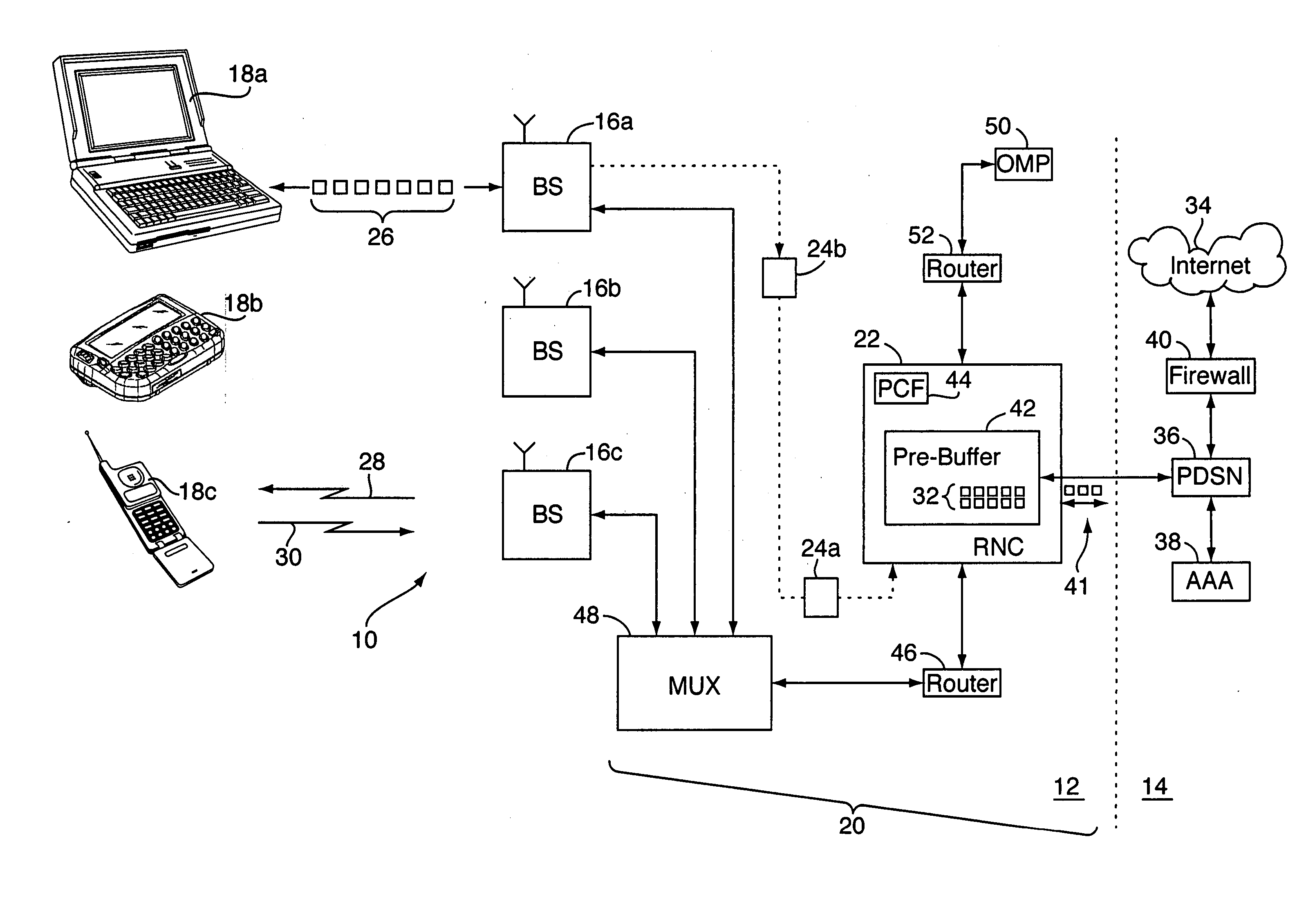
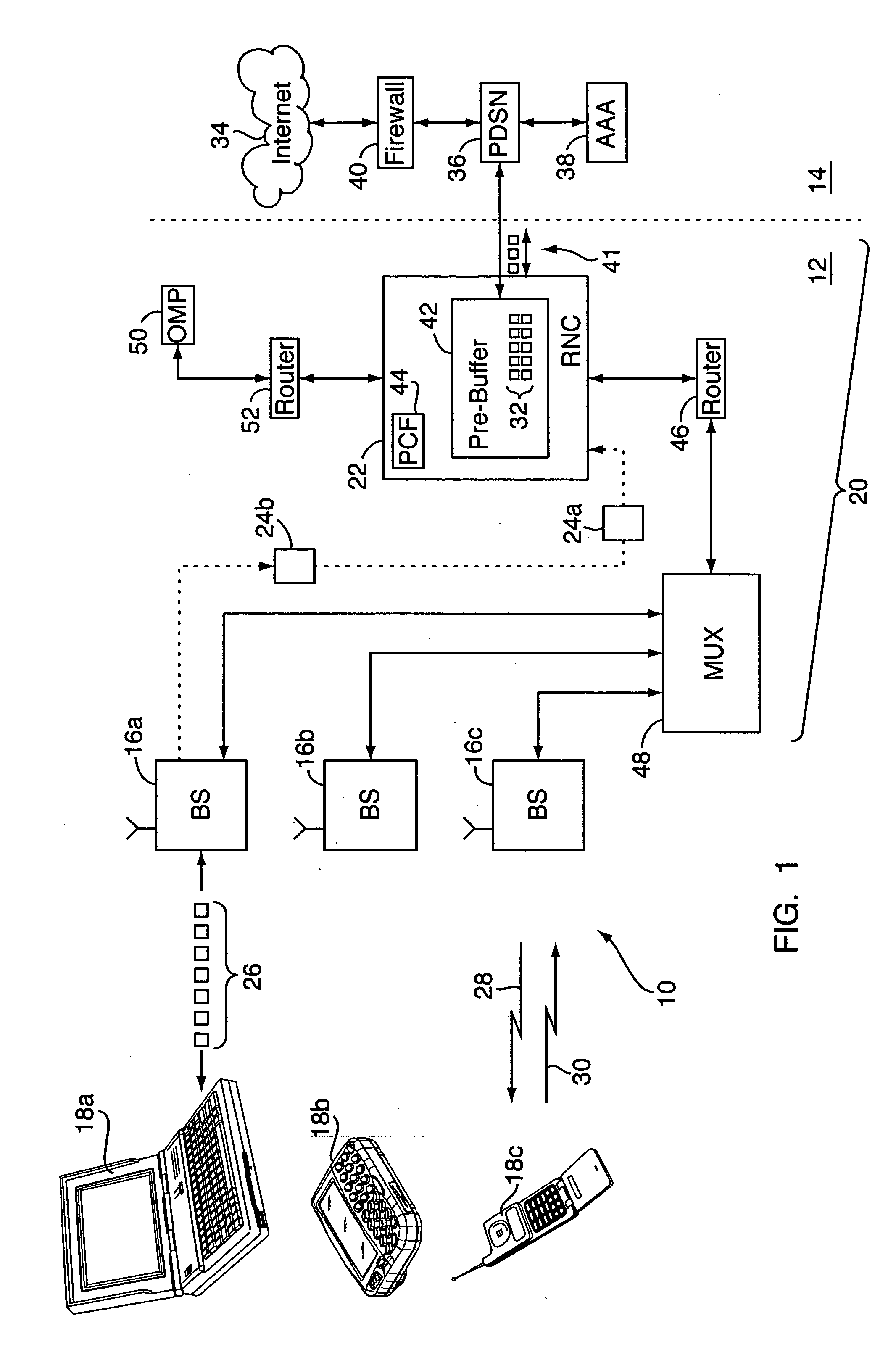
[0020] With reference to FIGS. 1-8, various embodiments of a method for measuring airlink transmission latency (and possibly other data transfer rate and related airlink characteristics) are implemented on or as part of a wireless communication network 10, e.g., a CDMA-based 1x-EVDO network or other wireless network. The wireless network 10 may include a radio access network portion (“RAN”) 12 and a core IP (Internet Protocol) network portion 14. The RAN 12 includes one or more fixed base stations 16a-16c (“BS”) each with various transceivers and antennae for radio communications with a number of distributed wireless units 18a-18c, e.g., mobile phones, “3-G” (third generation) wireless devices, wireless computer routers, and the like. The base stations 16a-16c are in turn connected to a RAN “front end”20, which may include a mobile switching center and / or radio network controller (“RNC”) 22 and other components which together act as the interface between the base stations 16a-16c an...


PUM


Abstract

In a method for determining transmission latency in a wireless network, data packets addressed to a wireless unit are received at a radio network controller (RNC) and forwarded to a base station in communication with the wireless unit for transmission over the forward link. The RNC keeps track of when it receives the packets. Periodically, the base station sends messages back to the RNC. Each message identifies a data packet and the time it was transmitted to the wireless unit. The RNC uses the messages to calculate a data transfer rate, e.g., the number of packets between the first packet received by the RNC and the packet identified in the message, divided by the time difference between the message and when the first packet was received by the RNC. The RNC then applies the transfer rate to any data remaining for the wireless unit, to determine the transmission latency thereof.

Description

FIELD OF THE INVENTION [0001] The present invention relates to communications and, more particularly, to wireless communication systems. BACKGROUND OF THE INVENTION [0002] Wireless, radio frequency communication systems enable people to communicate with one another over long distances without having to access landline-connected devices such as conventional telephones. While early systems were primarily configured for voice communications, technological improvements have enabled the development of “3-G” (third generation) and similar wireless networks for both voice and high-speed packet data transfer. For example, CDMA-based, “1x-EVDO” (Evolution Data Optimized, or Evolution Data Only) wireless communication networks, now implemented in many parts of the U.S. and elsewhere, use the CDMA2000® 3-G mobile telecommunications protocol / specification for the high-speed wireless transmission of both voice and non-voice data. 1x-EVDO is an implementation of CDMA2000® that supports high data ...

Claims


Application Information

Patent Timeline
Patent Type & Authority Applications(United States)
IPC IPC(8): H04Q7/24H04W24/08H04W92/12
CPCH04L43/0852H04W92/12H04W24/08H04L47/10
Inventor GANDHI, ASIF D.THOMAS, MATHEW
Owner LUCENT TECH INC
Why Eureka
Try Eureka