Communication Network, Communication Apparatus, Communication Control Method and Communication Control Program

a communication control and communication network technology, applied in the field of communication apparatus and communication network, can solve the problems of increasing the number of setting steps, affecting the accuracy of data links, and inability to perform automatic setting of parameters, so as to reduce the number of errors and the steps for setting the corresponding relations between data links and bundled links

Inactive Publication Date: 2007-10-04
NEC CORP
View PDF6 Cites 5 Cited by
  • Summary
  • Abstract
  • Description
  • Claims
  • Application Information

AI Technical Summary

Benefits of technology

[0035] With this, the communication apparatus as the master can collect the link information of the entire network. Thus, it is possible to perform automatic setting of SRLG that requires unique values to be set within the entire network.
[0036] With the present invention as described above, in a network using a plurality of data links in a single bundled link for routing, the transmission paths having the same port attribute within the own communication apparatus are bundled, the identification information is given to the bundled transmission paths, and the transmi

Problems solved by technology

Thus, it is likely to have setting errors, and the number of setting steps is increased.
Further, with the conventional LMP method, it is not possible to perform automatic setting of parameters, e.g. metric and SRLG which allot the values b

Method used


Image

  • Communication Network, Communication Apparatus, Communication Control Method and Communication Control Program
  • Communication Network, Communication Apparatus, Communication Control Method and Communication Control Program
  • Communication Network, Communication Apparatus, Communication Control Method and Communication Control Program

Examples


first embodiment

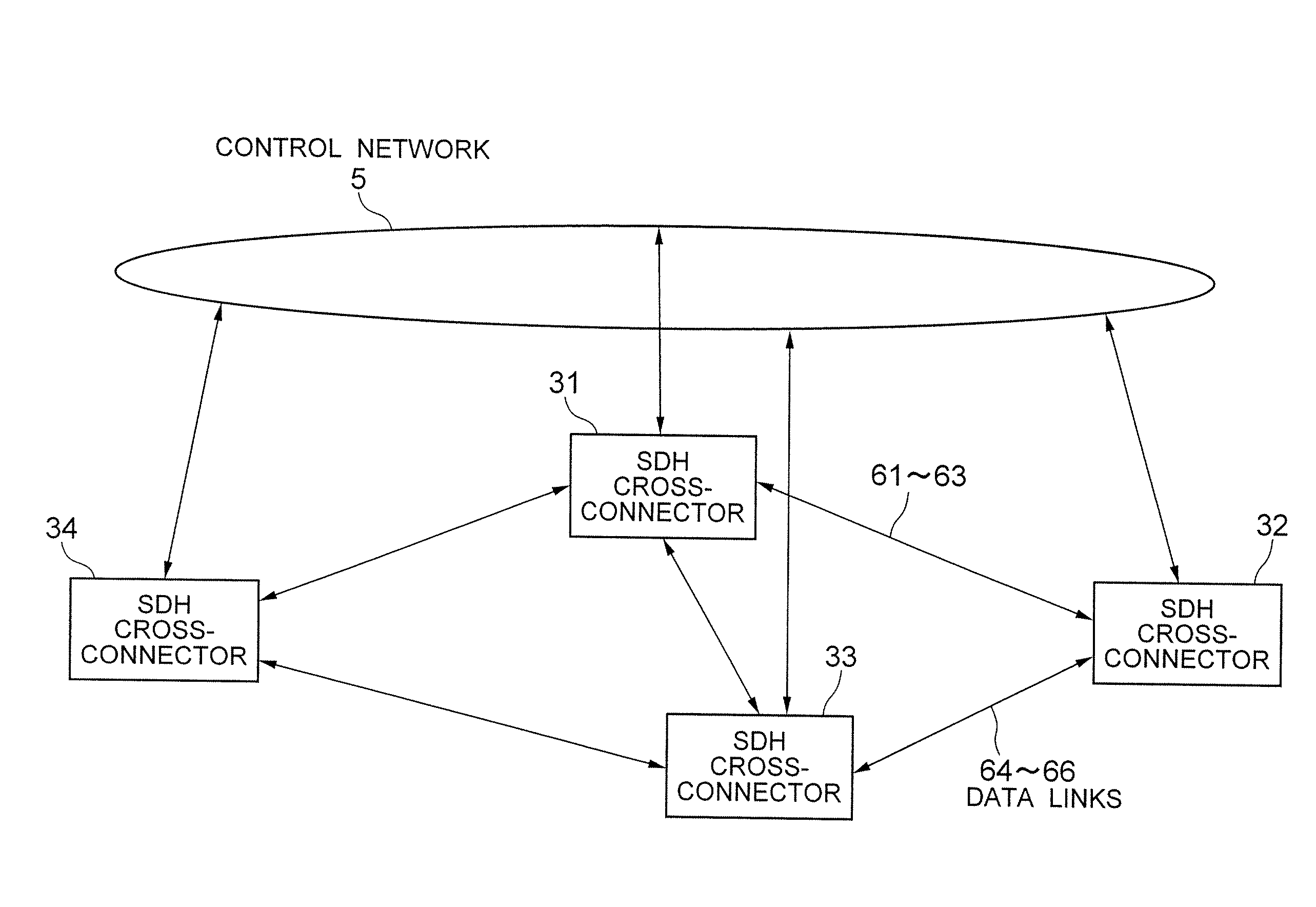
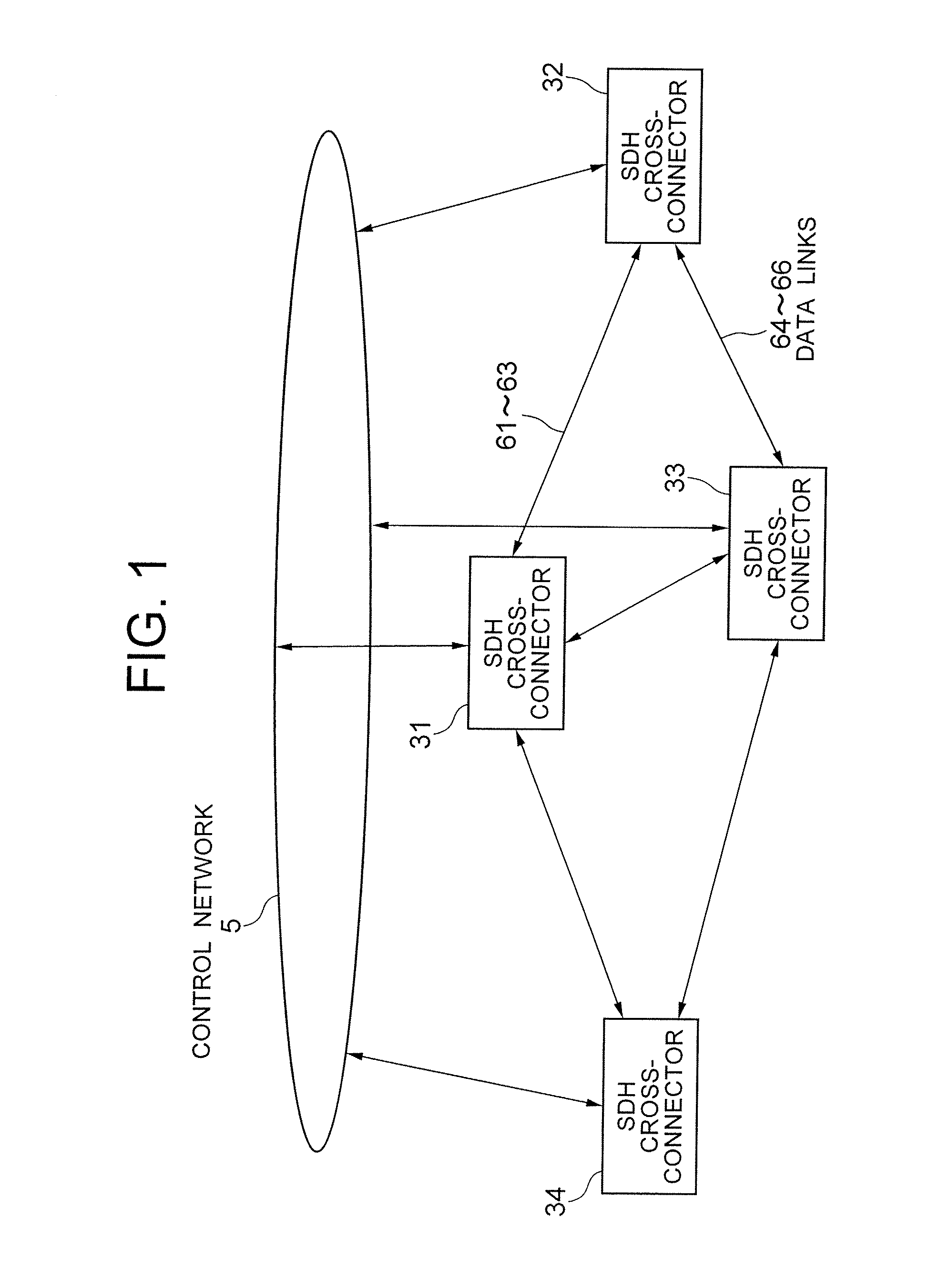
[0052]FIG. 1 is an overall block diagram for showing a communication network according to the present invention. Explanations will be provided hereinafter by referring to this drawing.

[0053] The communication network of this embodiment comprises: SDH cross-connectors 31-34; data links (transmission paths) 61-66, etc., which connect and transmit data between the neighboring SDH cross-connectors 31-34; and a control network 5 that is connected to each of the SDH cross-connectors 31-34 to be utilized for transmitting / receiving the control data. Although FIG. 1 only illustrates the connecting relations of the data links with respect to the neighboring SDH cross-connectors, there may actually also be a plurality of other data links as the physical connections than those shown therein. It is noted here that the SDH cross-connectors correspond to the communication apparatuses that constitute the communication network.

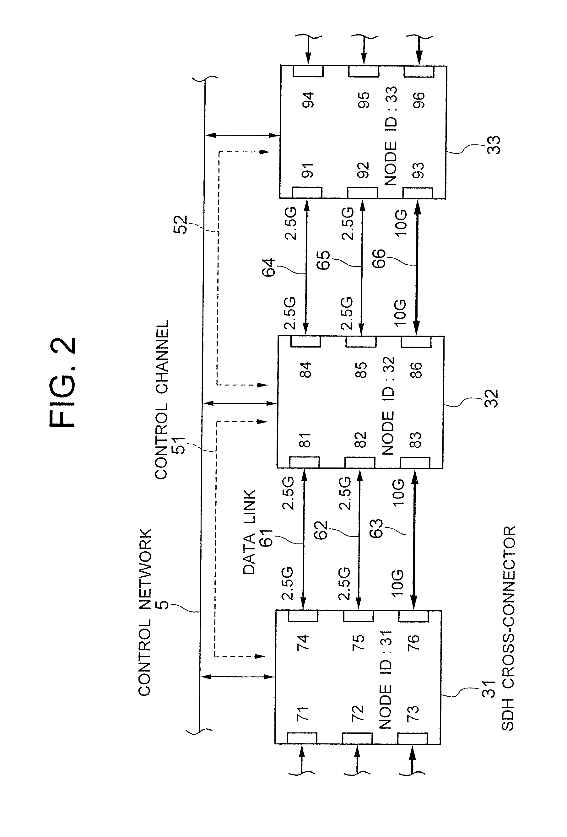
[0054]FIG. 2 is a network block diagram for showing the SDH cross-connec...

second embodiment

[0096]FIG. 11 is a functional block diagram for showing the SDH cross-connector of the communication network according to the present invention. Explanations will be provided hereinafter by referring to the drawing. Explanations for the same components as those of FIG. 1 and FIG. 3 are omitted by applying the same reference numerals thereto.

[0097] This embodiment comprises, in addition to the first embodiment shown in FIG. 3, a link information supply device 16, a link information forming unit 19, and an in-network bundled link database 211 in each of the SDH cross-connectors 31′-34′. In this embodiment, the SDH cross-connectors 31′-34′ comprise the link information forming unit 19, wherein one of the SDH cross-connectors serves as a master (master device), and the master node executes automatic setting of the link information. Illustrations of the SDH cross-connectors 31′, 33′, and 34′ will be omitted, since they may simply be in the same structure as that of the SDH cross-connecto...


PUM


Abstract

[PROBLEMS] To enable automatic setting of corresponding relations between data links and bundled links thereof.
[MEANS FOR SOLVING PROBLEMS] A temporary bundled link forming device (13) associates data links having the same port attributes within own communication apparatus with the identical temporary bundle link ID. A data link neighbor discovery device (11) obtains the neighboring node IDs of the data links. A bundled link forming device (14) automatically sets, as a bundled link, the data links having the same neighboring node IDs obtained by the data link neighbor discovery device (11), among the data links that are associated with the same temporary bundled link ID by the temporary bundled link forming device (13).

Description

TECHNICAL FIELD [0001] The present invention relates to a communication apparatus and a communication network, and to a control method and a control program thereof. More specifically, the present invention relates to a network automatic setting system and method for automatically setting relevance between a data link that transmits data and a bundled link to be advertised within a network. BACKGROUND ART [0002] In the next-generation network, there are used apparatuses constituted with various technologies, e.g. routers for switching packets, optical cross-connectors for switching wave paths, etc. For uniformly controlling such network constituted with different technologies, standardization of GMPLS (Generalized Multiprotcol Label Switching) has been carried out in IETF (Internet Engineering Task Force). [0003] A concept of TE link (a bundle of a plurality of links) is employed in the GMPLS. A plurality of data links are bundled to be treated as a single TE link, and it is used in...

Claims


Application Information

Patent Timeline
IPC IPC(8): H04L12/56
CPCH04L45/00H04L45/245Y02B60/33H04L45/50H04L45/28Y02D30/50
Inventor BABA, TERUYUKISUEMURA, YOSHIHIKOKAMI, NOBUHARUNISHIOKA, ITARU
Owner NEC CORP
Why Eureka
Try Eureka