Video decoding method and apparatus

a video and decoding technology, applied in the field of video decoding methods and apparatuses, can solve the problems of accumulating distortion at the time of decoding, increasing implementation costs, etc., and achieve the effect of reducing memory bandwidth

Inactive Publication Date: 2007-10-04
KK TOSHIBA
View PDF12 Cites 69 Cited by
  • Summary
  • Abstract
  • Description
  • Claims
  • Application Information

AI Technical Summary

Benefits of technology

[0013]FIG. 3 is a diagram illustrating a decoding operation of a video decoding apparatus making it possible to reduce a memory bandwidth.

Problems solved by technology

As a result, implementation costs increase.
In this way, the distortion occurring at the time of decoding is accumulated over time, and is felt as a big noise in a reconstructed picture.

Method used


Image

  • Video decoding method and apparatus
  • Video decoding method and apparatus
  • Video decoding method and apparatus

Examples


first embodiment

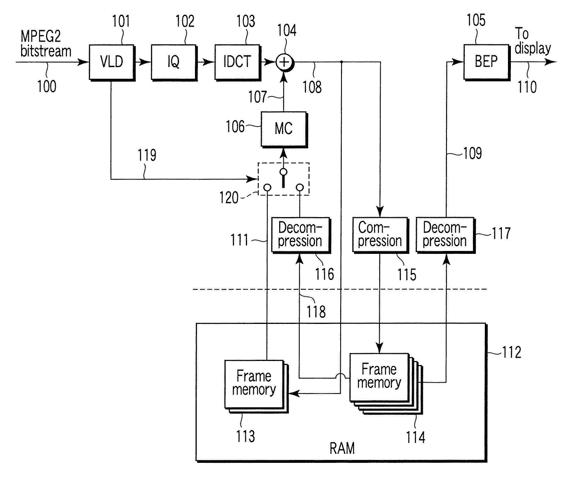
[0036]A video decoding apparatus of the first embodiment shown in FIG. 1 is supplied with video encoded data 100 (for example, MPEG-2 bit stream) generated by encoding a moving picture by an encoding system using motion compensated prediction such as MPEG-2. The video encoded data 100 is variable-length decoded by a variable length decoder 101, that is, subjected to a process of decoding a variable-length code. The variable length decoder 101 generates a quantized orthogonal transform coefficient (for example, DCT coefficient) and encoding mode information 119.

[0037]The encoding mode information 119 includes information representing a coding type of video encoded data, namely a coding type in picture unit (an encoded picture type), a coding type in pixel block unit (for example, in macroblock unit) (an encoding macroblock type) or a prediction mode in pixel block unit. The quantized orthogonal transform coefficient is dequantized by a dequantizer 102. The dequatized orthogonal trans...

second embodiment

[0140]FIG. 22 shows a video decoding apparatus according to the second embodiment. In the first embodiment shown in FIG. 1, in order to display a decoded picture, a compressed picture signal stored in the second frame memory 114 is read and decompressed with the second decompression device 117, and then send to the back-end processor 105 to generate the reconstructed picture signal 110. In contrast, in the second embodiment, the decoded picture signal 109 is read not from the second frame memory 114 storing compressed picture signals, but from the first frame memory 113 storing non-compression decoded picture signals as shown in FIG. 22, and supplied to the back end processor 105. Therefore, the second decompression device 117 in FIG. 1 is needless.

[0141]When the non-compression decoded picture signal is input to the back-end processor 105 of a display system in this way, it is possible to display a video that the compression noise is reduced and picture quality is not almost deteri...

third embodiment

[0142]FIG. 23 shows a video decoding apparatus according to the third embodiment. As is clear from the above description, in the first and second embodiments, there is trade off between the quality of the reconstructed picture signal 110, namely, picture quality of the display picture and the reduced amount of the memory bandwidth. The third embodiment makes it possible to select adaptively the methods of the first and second embodiment.

[0143]According to FIG. 23, there is provided a switch 121 which switches between the non-compression decoded picture signal read from the first frame memory 113 and the compressed / decompressed picture signal read from the second frame memory 114 and decompressed with the second decompression device 117 and supplies them to the back-end processor 105 selectively. On the basis of such a configuration, the switch 121 may be operated so that the compressed / decompressed picture signal from the second decompression device 117 is supplied to the back-end p...


PUM


Abstract

A video decoding apparatus includes a decoder to decode video encoded data using a predictive picture signal for a video signal, a compression device compressing the decoded picture signal, a first memory storing the decoded picture signal, a second memory storing the compressed picture signal, a decompression device decompressing the compressed picture signal read from the second memory, a selector selecting one of a decoded picture signal read from the first memory and a compressed/decompressed picture signal from the compression device as a reference picture signal according to at least one of a coding type of the video encoded data in picture unit and a prediction mode in block unit, and a motion compensator performing motion compensation on the reference picture signal to generate a predictive picture signal.

Description

CROSS-REFERENCE TO RELATED APPLICATIONS[0001]This application is based upon and claims the benefit of priority from prior Japanese Patent Application No. 2006-088883, filed Mar. 28, 2006, the entire contents of which are incorporated herein by reference.BACKGROUND OF THE INVENTION[0002]1. Field of the Invention[0003]The present invention relates to a video decoding method and an apparatus.[0004]2. Description of the Related Art[0005]A video encoding international standard system such as MPEG-2 (ISO / IEC 13818-2 | ITU-T Rec. H.262), MPEG-4 (ISO / IEC 14496-2), or H.264 (ITU-T Rec. H.2641 ISO / IEC 14496-10) adopts an inter-predictive encoding such as inter-frame or inter-field predictive encoding. In a decoding process of encoded video data based on inter-predictive encoding, a predictive picture is generated by motion compensation using a plurality of reference pictures of a plurality of frames stored in a picture memory.[0006]A picture memory for storing the reference pictures uses an e...

Claims


Application Information

Patent Timeline
Patent Type & Authority Applications(United States)
IPC IPC(8): H04N7/12H04N11/02H04N19/103H04N19/114H04N19/115H04N19/117H04N19/12H04N19/136H04N19/159H04N19/172H04N19/176H04N19/186H04N19/196H04N19/423H04N19/426H04N19/44H04N19/50H04N19/503H04N19/573H04N19/59H04N19/60H04N19/61H04N19/625H04N19/80H04N19/86H04N19/91
CPCH04N19/105H04N19/159H04N19/176H04N19/172H04N19/12H04N19/577H04N19/146H04N19/156H04N19/44H04N19/428H04N19/59H04N19/186H04N19/43H04N19/51
Inventor KOTO, SHINICHIROHIRAI, RYUSUKEYAMAGUCHI, NOBORUASANO, WATARU
Owner KK TOSHIBA
Why Eureka
Try Eureka