Method and system for performing interspinous space preparation for receiving an implant

a technology for implantable devices and surgical sites, applied in the field of method and system for preparing surgical sites for receiving implants, can solve the problems of not providing precise control over the positioning of the device, not allowing precise shaping or contouring of the spinous process, and affecting the patient's health

Active Publication Date: 2007-10-04
XTANT MEDICAL INC
View PDF83 Cites 134 Cited by
  • Summary
  • Abstract
  • Description
  • Claims
  • Application Information

AI Technical Summary

Benefits of technology

[0010] A sixth aspect of the present invention includes a bone cutting tool for preparing an implantation space. The bone cutting tool may be used accurately shape or contour the spinous processes defining an interspinous space. In one exemplary embodiment, a bone cutting tool is provided for preparing an interspinous space to receive an implantable device. The bone cutting tool may comprise a main body portion having first and second side walls and a front wall portion, the front wall portion configured to contact a bony surface to be shaped and a cutting element configured to shape the bony surface, the cutting element positioned between the first and second side walls on a front portion of the main body. In one exemplary embodiment, the front wall portion lies in a first plane and the cutting element lies in a second plane parallel to the first plane and spaced away from the first plane.
[0011] A seventh aspect of the present invention includes a bone cutting tool for preparing an implantation space. The bone cutting tool may be used accurately shape or contour the spinous processes defining an interspinous space. In one exemplary embodiment, a bone cutting tool is provided for preparing an interspinous space to receive an implantable device. The bone cutting tool may comprise a main body portion having first and second side walls, a rear wall, and a front wall portion, the front wall portion configured to contact a bony surface to be shaped and a cutting element configured to shape the bony surface, the cutting element positioned between the first and second side walls on a front portion of the main body. In one exemplary embodiment, the front wall portion is positioned a first distance from the rear wall and wherein the cutting element is positioned a second distance, greater than the first distance, from the rear wall.

Problems solved by technology

However, these freestyle methods do not allow precise shaping or contouring of the spinous processes, nor do they provide exact control over the positioning of the device.
Improper or incorrect placement of the device may lead to less than optimal results, including failure of the device, resulting in detrimental effects to the patient.

Method used


Image

  • Method and system for performing interspinous space preparation for receiving an implant
  • Method and system for performing interspinous space preparation for receiving an implant
  • Method and system for performing interspinous space preparation for receiving an implant

Examples


Embodiment Construction

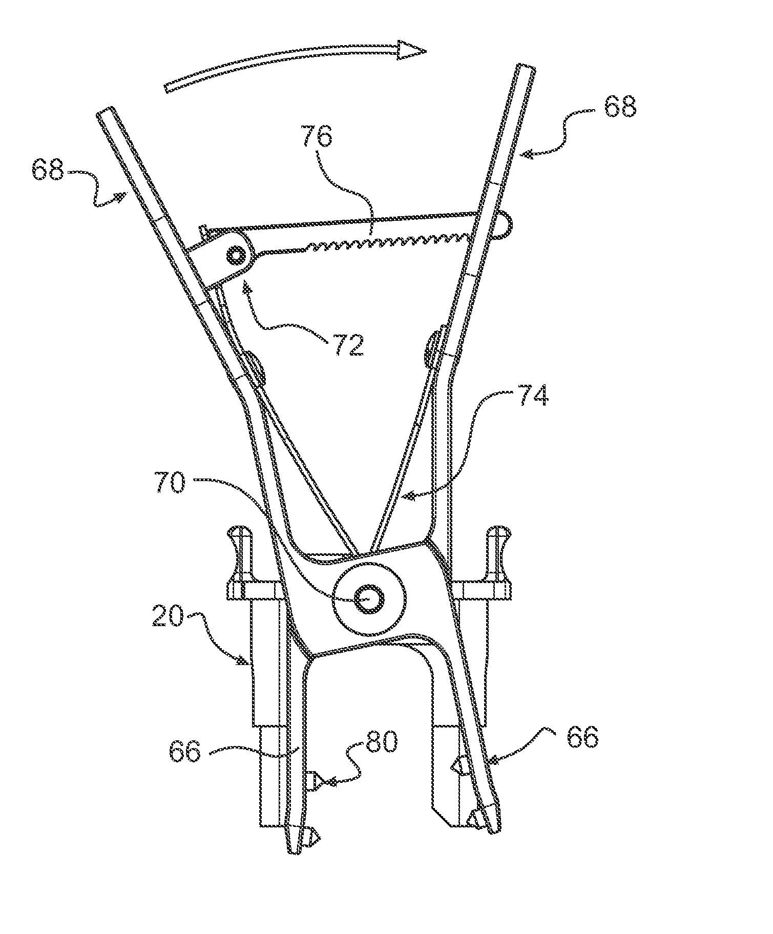
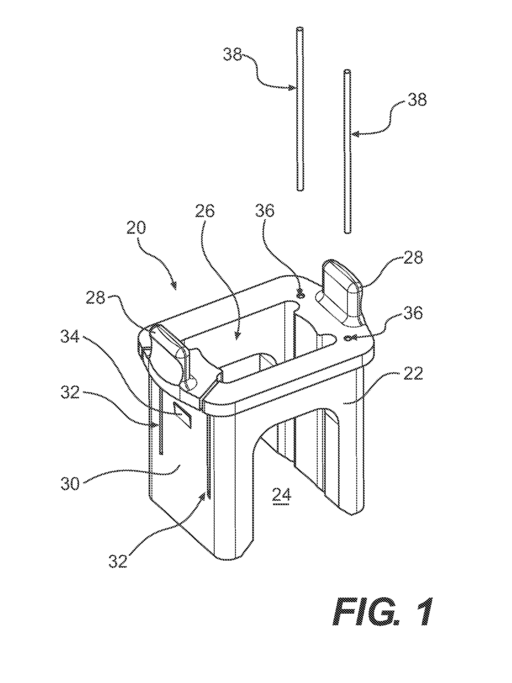
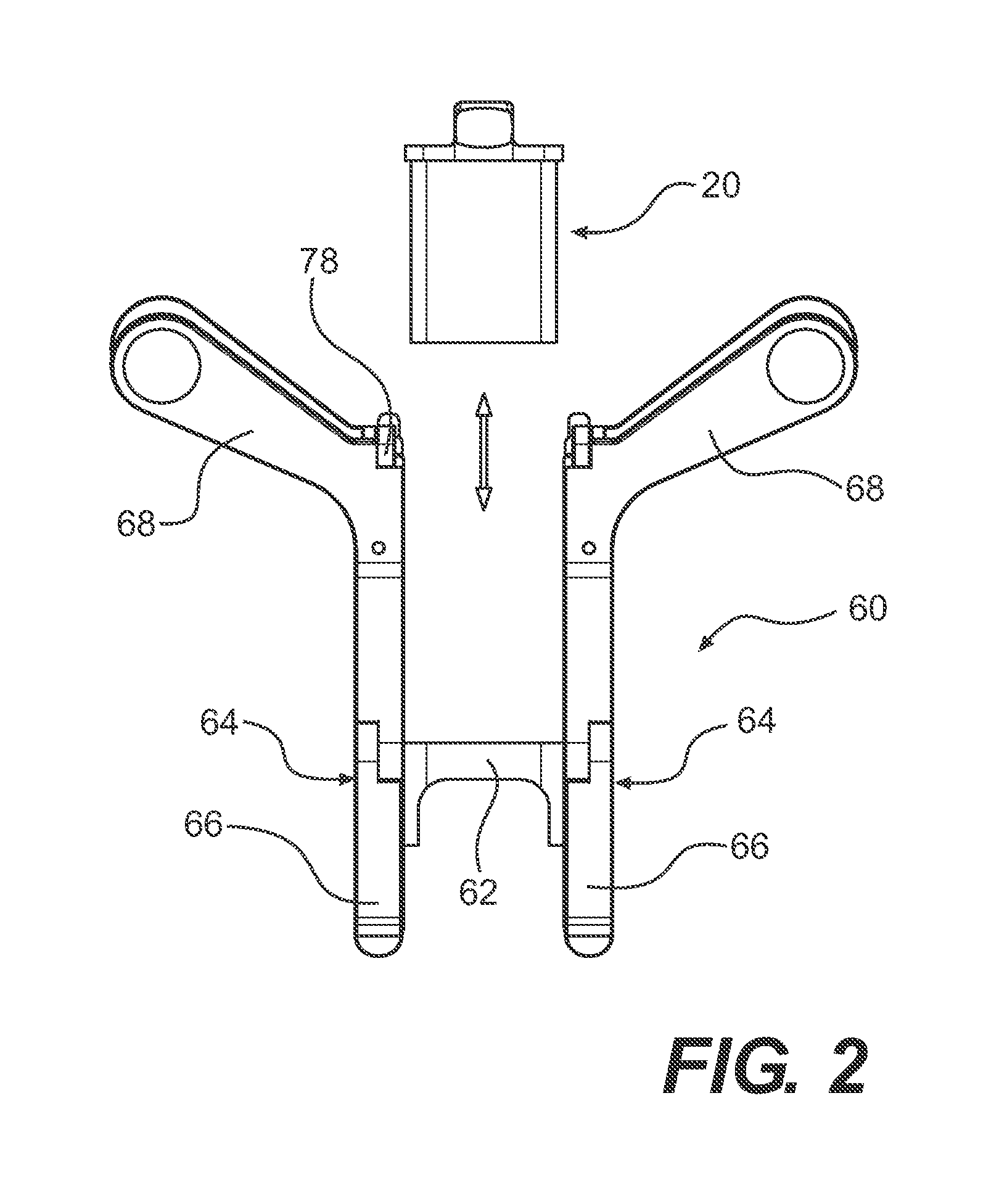
[0038]FIG. 1 illustrates an exemplary embodiment in which a cutting tool guide 20 includes a main body 22 having an aperture 24 extending therethrough. A portion of the aperture 24 is defined by a guiding surface 26. In one aspect of the invention, the cutting tool guide 20 includes two shaped guiding surfaces 26 that complement an outer surface of a cutting tool, such as for example, a blade 54 of a chisel 50 shown in FIG. 6. The guiding surfaces 26 serve as a predefined rail or slot in the cutting tool guide 20, against which the surgeon may direct the chisel 50 into the implantation site.

[0039] The cutting tool guide 20 may also include handles 28 for manipulating the guide 20 during use. The handles 28 may be shaped for easy gripping with fingers. The main body 22 may also include a depressible tab 30 formed on a side thereof. The depressible tab 30 may be defined by a pair of slots 32 located on the main body 22. A notch 34 may be included on the depressible tab 30 to allow th...


PUM


Abstract

A method and system are provided for preparing an interspinous space to receive an implantable device. The system may comprise a cutting tool guide having a guiding surface for directing a cutting tool therethrough and a holder for positioning the cutting tool guide relative to the interspinous space. The holder may be configured to adjustably attach to at least one of a pair of spinous processes defining the interspinous space.

Description

[0001] This application claims priority under 35 U.S.C. §119 based on U.S. Provisional Application No. 60 / 774,571, filed Feb. 17, 2006, the complete disclosure of which is incorporated herein by reference.FIELD OF THE INVENTION [0002] The present invention relates to a method and system for preparing a surgical site for receiving an implantable device. Specifically, the present invention relates to a method and system for preparing the interspinous space, including the spinous processes, for receiving an interspinous stabilization device. BACKGROUND OF THE INVENTION [0003] Conventional methods for implanting interspinous devices provide little or no control over the exact positioning of the device in an implantation site. Typically, if the surgeon desires more surface contact between the device and the bony surface of the spinous processes, the surgeon can remove bone tissue using a cutting tool such as, for example, a chisel, luer plier, or power cutting tool. However, these freest...

Claims


Application Information

Patent Timeline
Patent Type & Authority Applications(United States)
IPC IPC(8): A61B17/00
CPCA61B17/1604A61B17/1671A61B17/7064A61B17/7047A61B2019/5416A61B17/1757A61B2017/320052A61B2090/3916A61F2/4611A61F2/4684
Inventor BERTAGNOLI, RUDOLFEISEN, GUNTMAR H.SCHURRER, NINATRAUTWEIN, FRANK T.VISCOGLIOSI, MARC R.
Owner XTANT MEDICAL INC
Why Eureka
Try Eureka