Interchangeable sight system and method for removably mounting an optical alignment apparatus

a technology of optical alignment and interchangeable sight, which is applied in the direction of sighting devices, weapons, weapon components, etc., can solve the problems of inconvenient adjustment, inconvenient adjustment, and inconvenient adjustment of the prior art removable sight mount, so as to achieve convenient changes and precise and convenient sight adjustment

Active Publication Date: 2007-10-11
KENGS FIREARMS SPECIALTY
View PDF16 Cites 64 Cited by
  • Summary
  • Abstract
  • Description
  • Claims
  • Application Information

AI Technical Summary

Benefits of technology

[0015] Accordingly, it is a primary object of the present invention to overcome the above mentioned difficulties by providing a method and interchangeable apparatus permitting the user to rig

Problems solved by technology

While the combat sights of the prior art do provide a smooth and snag-free draw, a clear sight picture and rugged service, they often do not provide a wide enough range of adjustability and are not readily changed with other sights, since sights are often installed by gunsmiths using specialized tools.
Those removable sight mounts

Method used


Image

  • Interchangeable sight system and method for removably mounting an optical alignment apparatus
  • Interchangeable sight system and method for removably mounting an optical alignment apparatus
  • Interchangeable sight system and method for removably mounting an optical alignment apparatus

Examples


Embodiment Construction

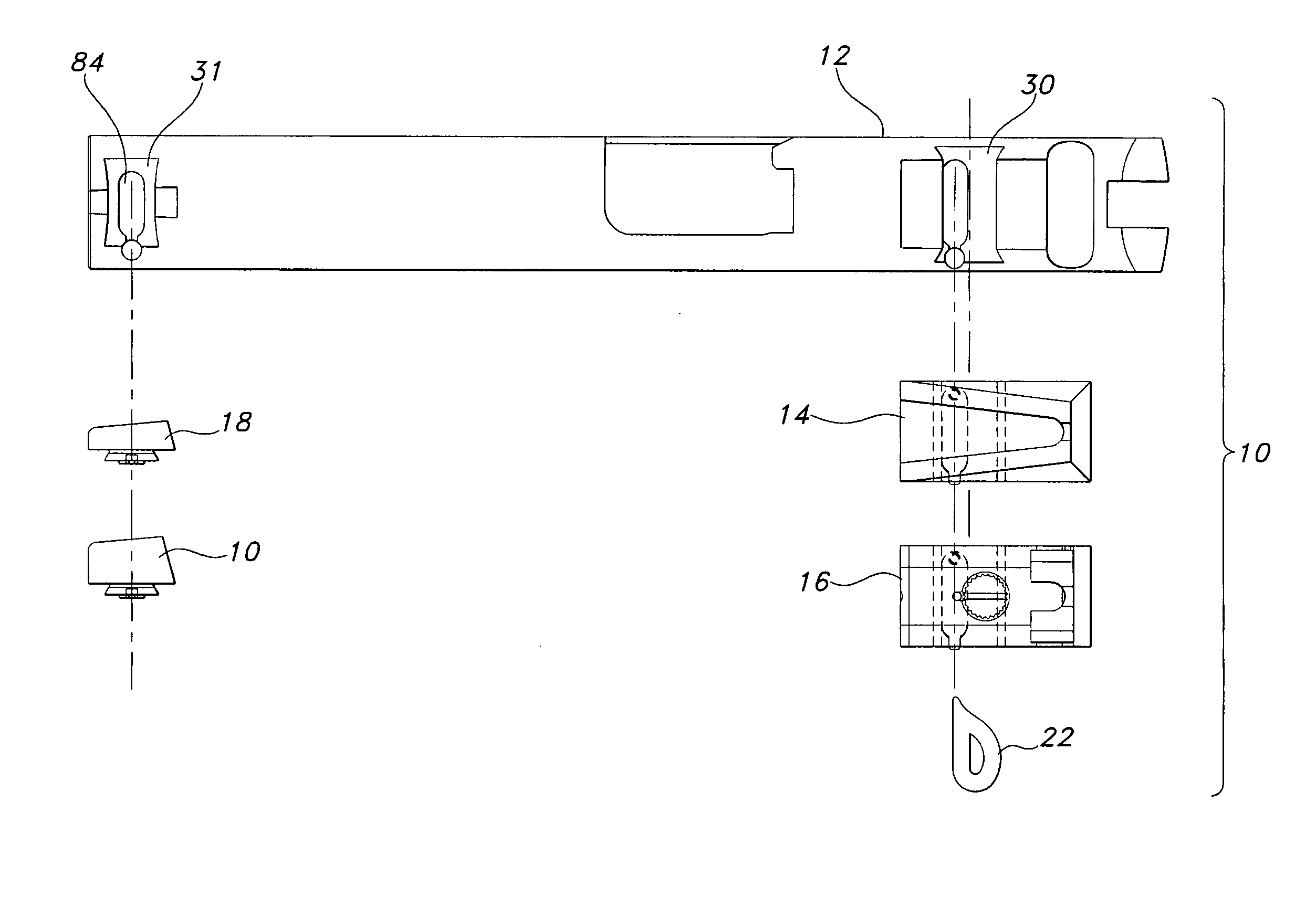
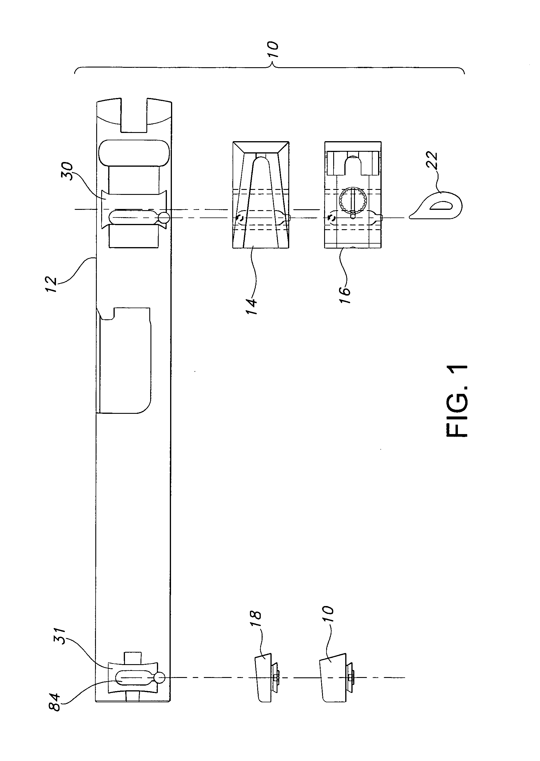
[0038] Referring now to FIGS. 1 through 8 of the accompanying drawings, the interchangeable sight system 10 of the present invention preferably includes a pistol slide or firearm 12 (e.g., a pistol slide or firearm receiver) having a transverse receiving notch 30. As above, “transverse” means in a left-right direction at a right angle to the pistol bore's central axis and lying in a horizontal plane when the pistol is held in a standard upright grip with the bore central axis in a horizontal plane.

[0039] As best seen in FIG. 1, sight system 10 can be embodied as a kit including a plurality of rear sights (e.g., fixed rear sight 14 and adjustable rear sight 16) and a plurality of front sights (e.g., a short front blade 8 and a taller front blade 20), as well as a sight unlocking / removal tool 22.

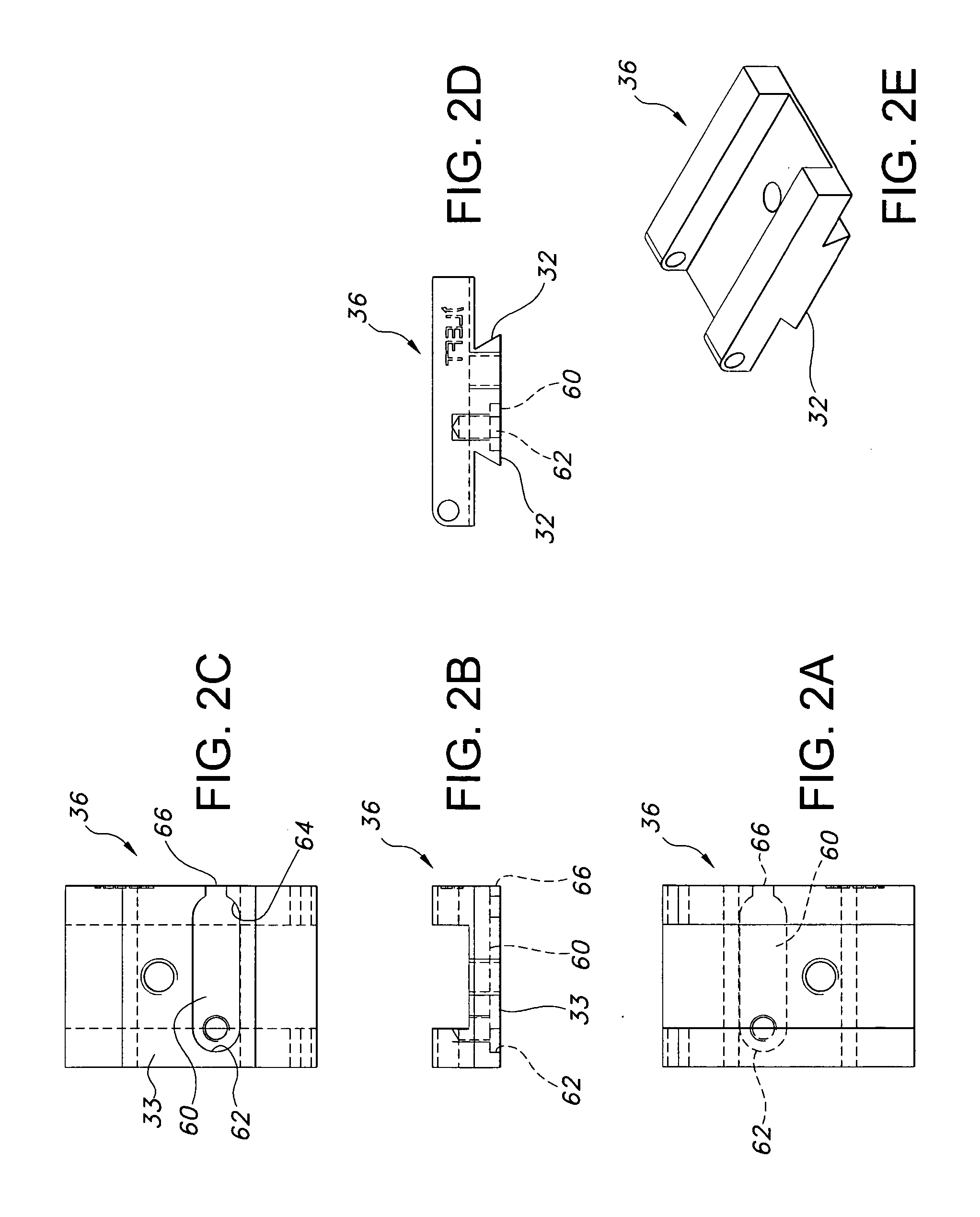
[0040] Generally, the standardized dimensions for receiving notch 30 (as best seen in FIGS. 1, 4a and 4b) define a configuration adapted to accept a Novak-style dovetail-like sight projectio...


PUM


Abstract

A rugged, releasably attachable or interchangeable optical alignment system well suited for use as with pistol sights includes a sight body carrying a leaf spring locking member adapted to releasably engage a pistol's indentation. The sight body's leaf spring member is inserted into the pistol in a side opening transverse receiving notch with a pinned end of the leaf spring locking member sliding transversely over the pistol indentation's end wall open segment (at the side of the pistol). The user slides the sight base toward the bore's central axis to its fullest transverse extent, whereupon the leaf spring member's first end abuts the indentation's closed end wall. At this moment, the leaf spring locking member's free distal second end springs down and releasably engages and abuts the indentation's end wall, thus releasably locking the sight base to the pistol.

Description

CROSS-REFERENCE TO RELATED APPLICATIONS AND CLAIM TO PRIORITY [0001] This application claims benefit (under 35 U.S.C. §§ 119(e) and 120) of and priority to U.S. provisional patent application No. 60 / 602,886, filed Aug. 20, 2004, the entire disclosure of which is incorporated herein by reference.BACKGROUND OF THE INVENTION [0002] 1. Field of the Invention [0003] The present invention relates to an interchangeable, adjustable support or mount for an optical alignment device such as a firearm sight and a method for removeably mounting optical devices such as gun sights on pistols or other firearms. [0004] 2. Discussion of the Prior Art [0005] At present, a wide variety of optical sights are available for use on firearms such as pistols. [0006] A typical handgun or pistol has optical alignment fixtures or sights including a front sight and a rear sight which are aligned with one another to form a sight picture for aligning the pistol's point of aim on the target. Prior art pistol sights...

Claims


Application Information

Patent Timeline
IPC IPC(8): F41G1/033F41G1/16F41G1/00
CPCF41G1/28F41G1/02
Inventor KIDD, ANTHONY WAYNE
Owner KENGS FIREARMS SPECIALTY
Why Eureka
Try Eureka