Operating pedal support structure

a technology for supporting structures and pedals, which is applied in the direction of pedestrian/occupant safety arrangements, mechanical control devices, instruments, etc., can solve the problems of affecting jeopardizing the driver's pedal operation feeling, and difficulty in maintaining the comfort of pedal operation. , to achieve the effect of comfortable pedal operation

Active Publication Date: 2007-10-11
MAZDA MOTOR CORP
View PDF10 Cites 12 Cited by
  • Summary
  • Abstract
  • Description
  • Claims
  • Application Information

AI Technical Summary

Benefits of technology

[0012]In light of the aforementioned requirements and problems of the prior art, it is an object of the present invention to provide a support structure for an operating pedal which can prevent a rearward displacement of a tread plate of a pedal unit as well as an unexpected downward displacement of the pedal unit in the event of a collision of a vehicle, yet providing a comfortable feeling of pedal operation.

Problems solved by technology

In the aforementioned arrangement of JP No. 2005-510785, the supporting shaft of the pedal unit is normally supported by the pivotable lever, so that an external force exerted on the pedal unit, for instance, tends to produce irregular movements of the pivotable lever, potentially causing the pedal unit to be supported in an unstable state and jeopardizing the driver's feeling of pedal operation.
This makes it difficult to properly maintain comfortable operability of the pedal unit.
Also, the operating pedal support structure of EP0659615 has a problem that it is difficult to disengage the pedal unit from the pedal bracket in a reliable fashion if the pedal unit becomes aslant when the arms of the pedal bracket deform and become separated apart in the event of a vehicle collision.

Method used


Image

  • Operating pedal support structure
  • Operating pedal support structure
  • Operating pedal support structure

Examples


first embodiment

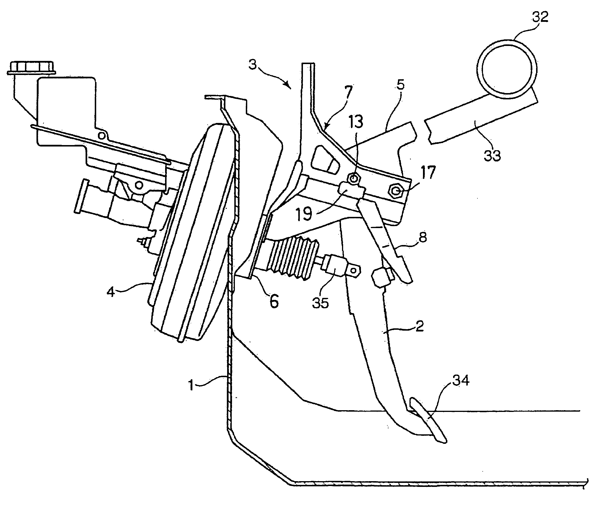
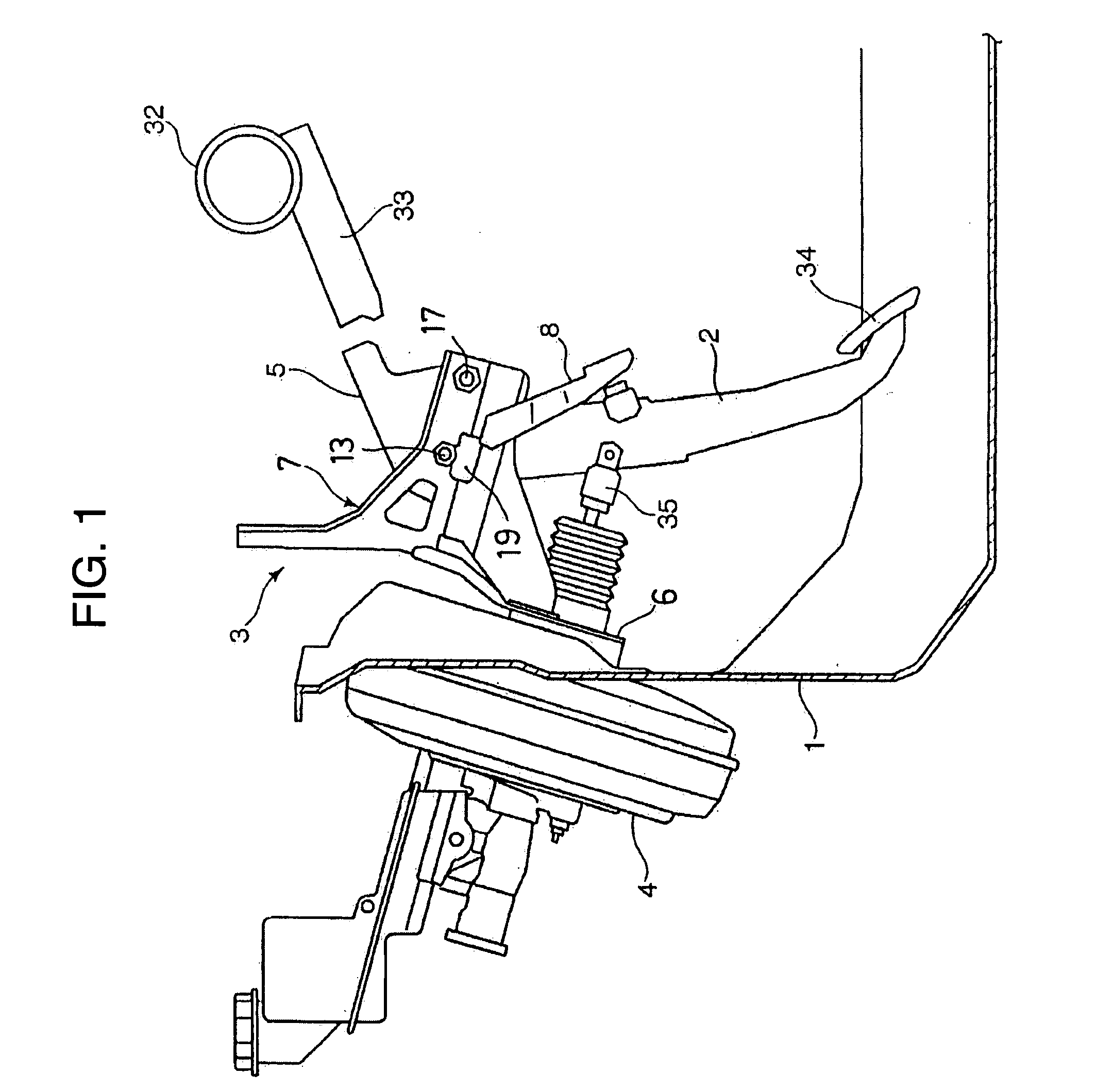
[0048]FIG. 1 is a partially sectional side view of a support structure for an operating pedal of a vehicle according to a first embodiment of the invention, in which designated by the reference numeral 1 is a dash panel which separates the vehicle interior from an engine room, the operating pedal support structure including a pedal bracket 3 fixed to a rear side of the dash panel 1 with a brake booster 4 fixed to a front side of the dash panel 1, as well as a pedal unit 2 and a pivotable lever 5, both of which are mounted pivotably in a plane parallel to a longitudinal direction of the vehicle body. In the present and following embodiments, the operating pedal having the pedal unit 2 the pedal bracket 3 as principal elements described hereinafter, by way of example, is a foot-operated brake pedal for engaging brakes as illustrated.

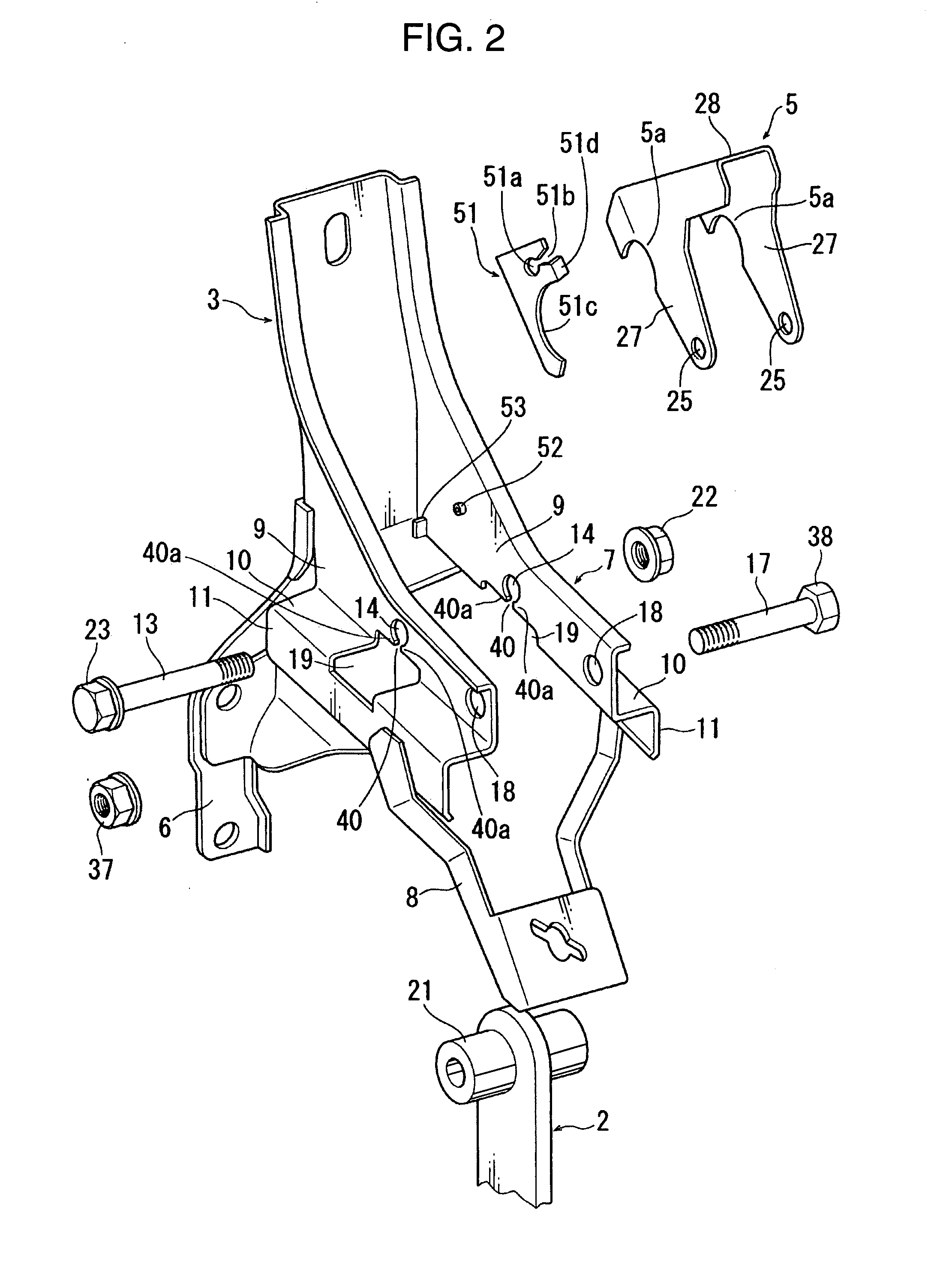
[0049]As shown in FIG. 2, the pedal bracket 3 includes a mounting base plate 6 which is firmly bolted to the dash panel 1 and a bracket frame 7 having lef...

second embodiment

[0064]FIGS. 8 and 9 are diagrams showing an operating pedal support structure according to a second embodiment of the invention, in which elements like those of the first embodiment are designated by the same symbols and a detailed description of such elements are not given below again.

[0065]In this embodiment, the shaft retainers 51 of the first embodiment are replaced by shaft retainers 61. These shaft retainers 61 are elongate, leverlike narrow members attached to the pivotable lever 5 pivotably on short supporting pins 62 which protrude laterally outward from outside surfaces of the pivotable lever 5 close to a forward end thereof. Under normal conditions, each shaft retainer 61 is held stationary in a position shown in FIG. 8 without pivoting unless a relatively large force is applied (as in the following embodiments employing supporting pins of a like structure).

[0066]The shaft retainers 61 held by the pivotable lever 5 pivotably thereon each have a retaining part 61c (which c...

third embodiment

[0069]FIGS. 10 and 11 are diagrams showing an operating pedal support structure according to a third embodiment of the invention, in which elements like those of the foregoing embodiments are designated by the same symbols and a detailed description of such elements are not given below again.

[0070]The third embodiment is similar to the second embodiment in that shaft retainers 71 (which correspond to the shaft retainers 51, 61 of the first and second embodiments) are fixed to the pivotable lever 5 by respective supporting pins 72 which protrude laterally outward from the pivotable lever 5. The shaft retainers 71 each have a retaining part 71c which is located immediately below one of the boss portions 21 of the first pivot shaft 13 under normal conditions, but there is not provided any projecting part corresponding to the stopper pin 63 of the second embodiment on either bracket arm of the bracket frame 7 of the pedal bracket 3. In the operating pedal support structure of this embod...


PUM


Abstract

A pedal bracket (3) affixed to a dash panel (1) pivotably supports a pedal unit (2) via a first pivot shaft (13) and a pivotable lever (5) via a second pivot shaft (17). A shaft retainer (51) prevents a downward displacement of the first pivot shaft (17) under normal conditions, whereas the pivotable lever (5) goes into contact with a side member (33) of a vehicle body and pivots on the second pivot shaft (17) in a specific direction in the event of a vehicle collision, thereby thrusting and displacing the first pivot shaft (13) downward and disengaging the pedal unit (2) from the pedal bracket (3). At this time, the shaft retainer (51) draws back from underneath the first pivot shaft (13), for instance, as a result of pivoting of the pivotable lever (5) and goes into a nonrestrictive state in which the shaft retainer (51) allows a displacement of the first pivot shaft (13).

Description

BACKGROUND OF THE INVENTION[0001]1. Field of the Invention[0002]The present invention relates to a support structure for an operating pedal of a vehicle.[0003]2. Description of the Related Art[0004]A conventionally known support structure for an operating pedal of a vehicle, such as a brake pedal or a clutch pedal, is such that a foot-operated pedal unit with a tread plate provided at a lower end is pivotably supported by a pedal bracket which is fixed to a dash panel, allowing a driver to pivot the operating pedal along a longitudinal direction of the vehicle. This structure permits the pedal unit which is supported by the pedal bracket at an upper end via a laterally extending first pivot shaft to pivot along the longitudinal direction of the vehicle when the driver presses down on the tread plate by the foot. In the design of this kind of operating pedal support structure, it is required that the pedal unit will not be greatly displaced rearward in the event of a collision (espec...

Claims


Application Information

Patent Timeline
Patent Type & Authority Applications(United States)
IPC IPC(8): G05G1/14G05G1/30
CPCB60R21/09Y10T74/20528Y10T74/20888B60T7/065
Inventor TOKUMO, MASAYUKIMATSUOKA, TOSHIHIROMIYOSHI, KEISUKE
Owner MAZDA MOTOR CORP
Why Eureka
Try Eureka