Electrical hand-held tool with a cooling fan

a technology of hand-held tools and cooling fans, which is applied in the direction of portable power-driven tools, portable percussive tools, turning instruments, etc., can solve the problem that a substantial portion of the cooling air flow cannot escape, and achieve the effect of high air overpressur

Inactive Publication Date: 2007-10-11
HILTI AG
View PDF24 Cites 18 Cited by
  • Summary
  • Abstract
  • Description
  • Claims
  • Application Information

AI Technical Summary

Benefits of technology

[0019]Advantageously, there are provided several cooling air conduits which permits to transpor...

Problems solved by technology

Thereby only unsubstantial portion of the cooli...

Method used


Image

  • Electrical hand-held tool with a cooling fan
  • Electrical hand-held tool with a cooling fan
  • Electrical hand-held tool with a cooling fan

Examples


Embodiment Construction

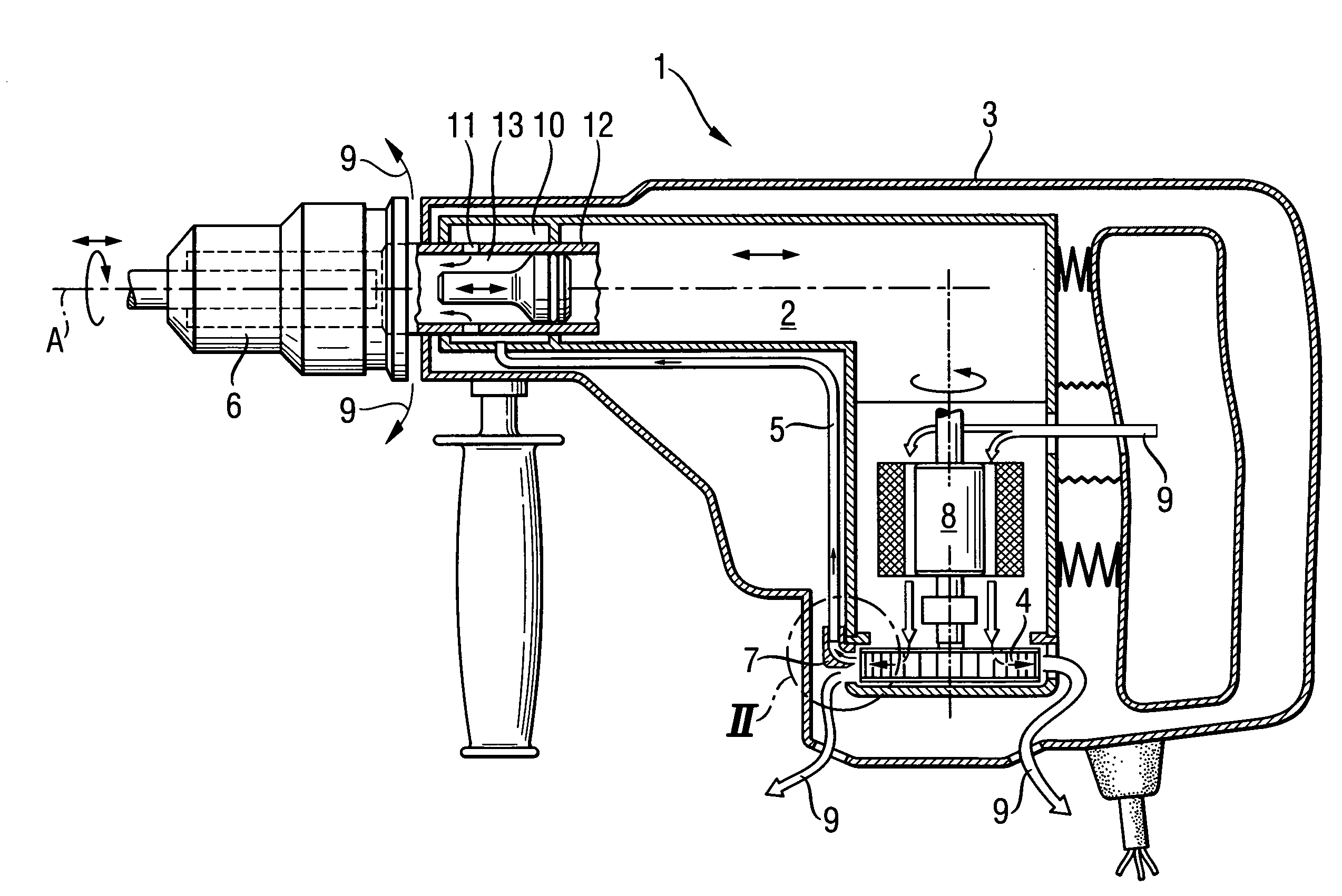
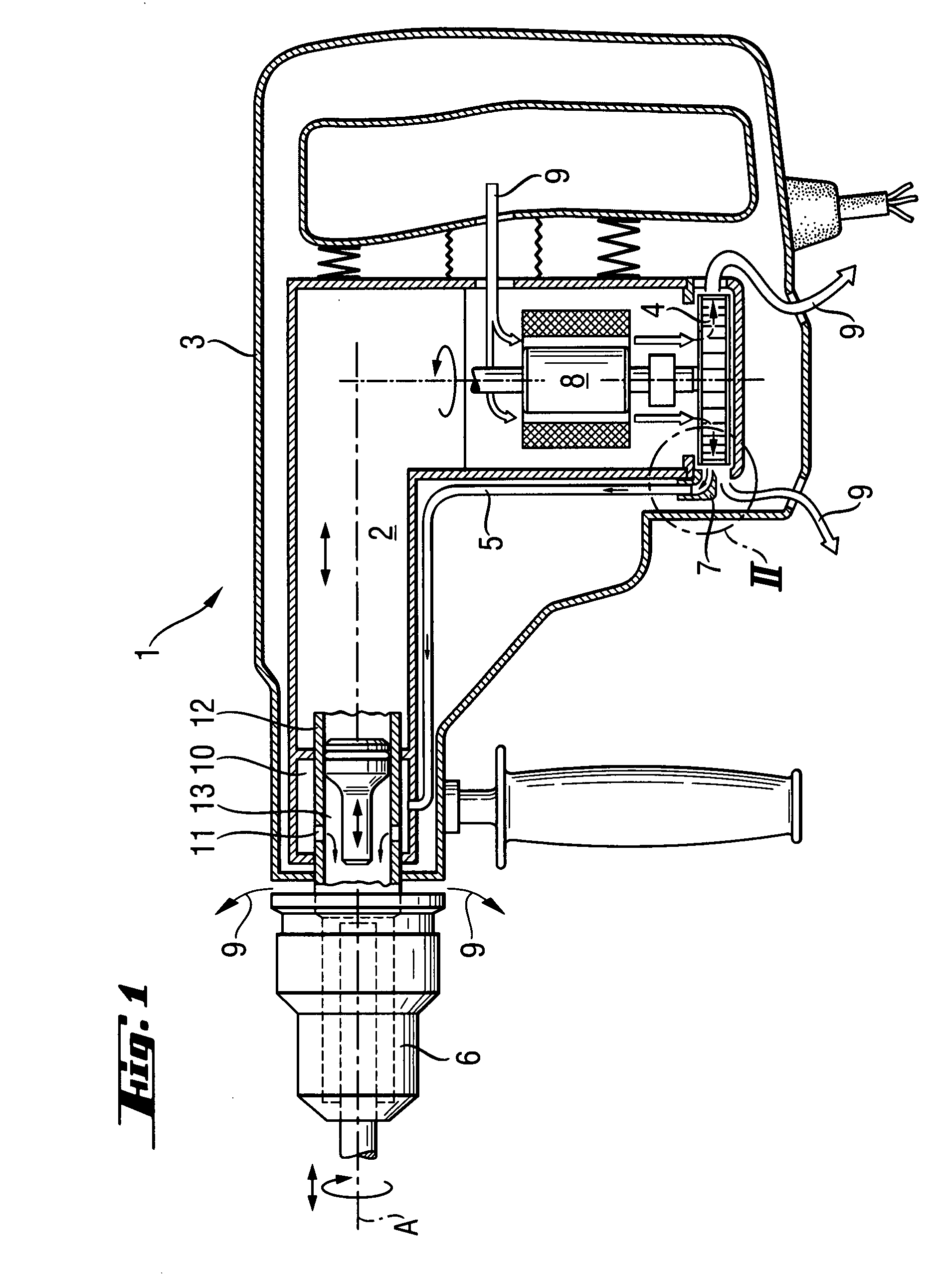
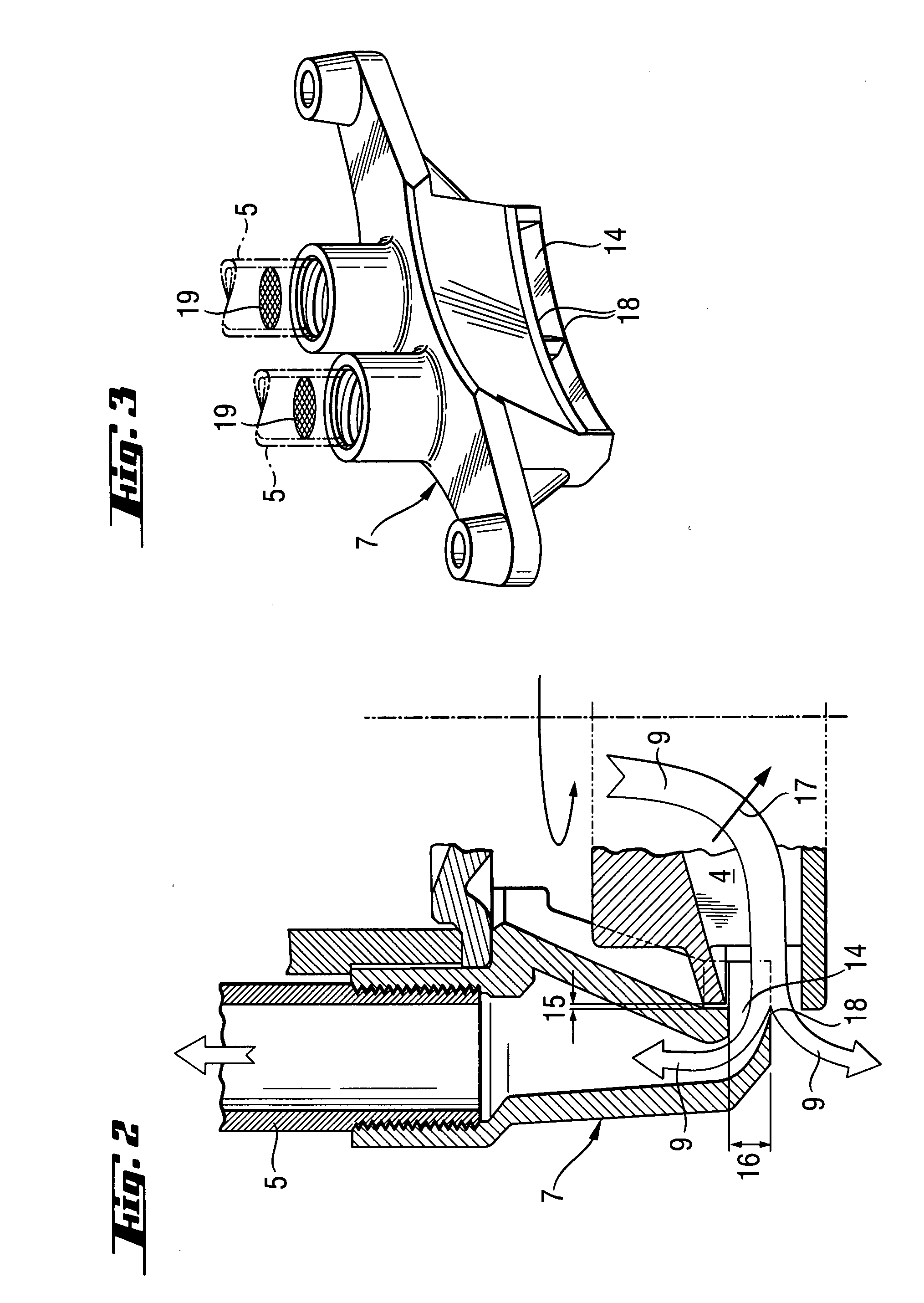
[0025]An electrical hand-held tool 1, which is shown in FIG. 1, includes an outer housing 3, a working tool-side assembly 2 in form of a percussion mechanism assembly that is supported in the outer hosing 3 for a limited axial displacement therein and that imparts blows along a rotational axis A, and an inner cooling fan 4 in form of a centrifugal blower located in a cooling air conduit. The cooling air conduit 5 extends between the working tool-side end of the working tool-side assembly 2 at which a chuck 6 is secured, and the cooling fan 4. At the fan side, the cooling air conduit 5 includes barrier means 7. A small portion of a cooling air 9 which is aspirated by the cooling fan 4 through the outer housing 3 and a substantial portion of which, after cooling an electric motor 8, is blown out, enters, through the barrier means 7, the tubular cooling air conduit 5, an air-tight annular space 10, and openings 11 of a guide tube 12 into the antechamber of a die 13 axially displaceable...


PUM

PropertyMeasurementUnit
Widthaaaaaaaaaa

Abstract

An electrical hand-held tool (1) includes a working tool-side assembly (2) located in the tool outer housing (3), a cooling fan (4) also located in the outer housing (3), at least one cooling air conduit (5) extending between a working tool-side end of the assembly (2) and the cooling fan (4), and barrier element (7) provided on a cooling fan-side of the cooling air conduit (5) in the vicinity of the cooling fan (4) and having a barrier opening (14) that opens toward the cooling fan (4).

Description

BACKGROUND OF THE INVENTION[0001]1. Field of the Invention[0002]The present invention relates to an electrical hand-held tool such as chisel hammer, combination hammer, compass saw, saber saw, etc., with a cooling fan for producing a cooling air flow for cooling the tool motor.[0003]2. Description of the Prior Art[0004]With the electrical hand-held tools, and with cooling high-power electric motors, if needed, the outgoing air is put to other uses. E.g., in U.S. Pat. No. 6,126,368, the outgoing air is used for blowing over a working tool or a workpiece.[0005]According to German publication DE 19626254, a warm outgoing air flows under a slight air overpressure through a cooling channel between the percussion mechanism assembly and the outer housing up to a working tool-side striking tool holder provided on the spindle, being used there for cooling the outer surface of the guide sleeve that became very heated as a result of sliding friction resulting from an axial limited displacement...

Claims


Application Information

Patent Timeline
IPC IPC(8): B23B51/06B23B27/10
CPCB25D17/06B25D17/20B25D2217/0061Y10T408/46B25D2250/245B25F5/008Y10T408/453B25D2250/095
Inventor OHLENDORF, OLIVER
Owner HILTI AG
Why Eureka
Try Eureka