
Debugging functionality embedded in an application

a debugging functionality and application technology, applied in the field of data processing, can solve the problems of difficult to track down runtime problems in complex multi-threaded or distributed systems, and difficult to track down debugging problems occurring in production environments

Active Publication Date: 2007-10-11
ORACLE CORPORATION +1
View PDF25 Cites 48 Cited by
  • Summary
  • Abstract
  • Description
  • Claims
  • Application Information

AI Technical Summary

Benefits of technology

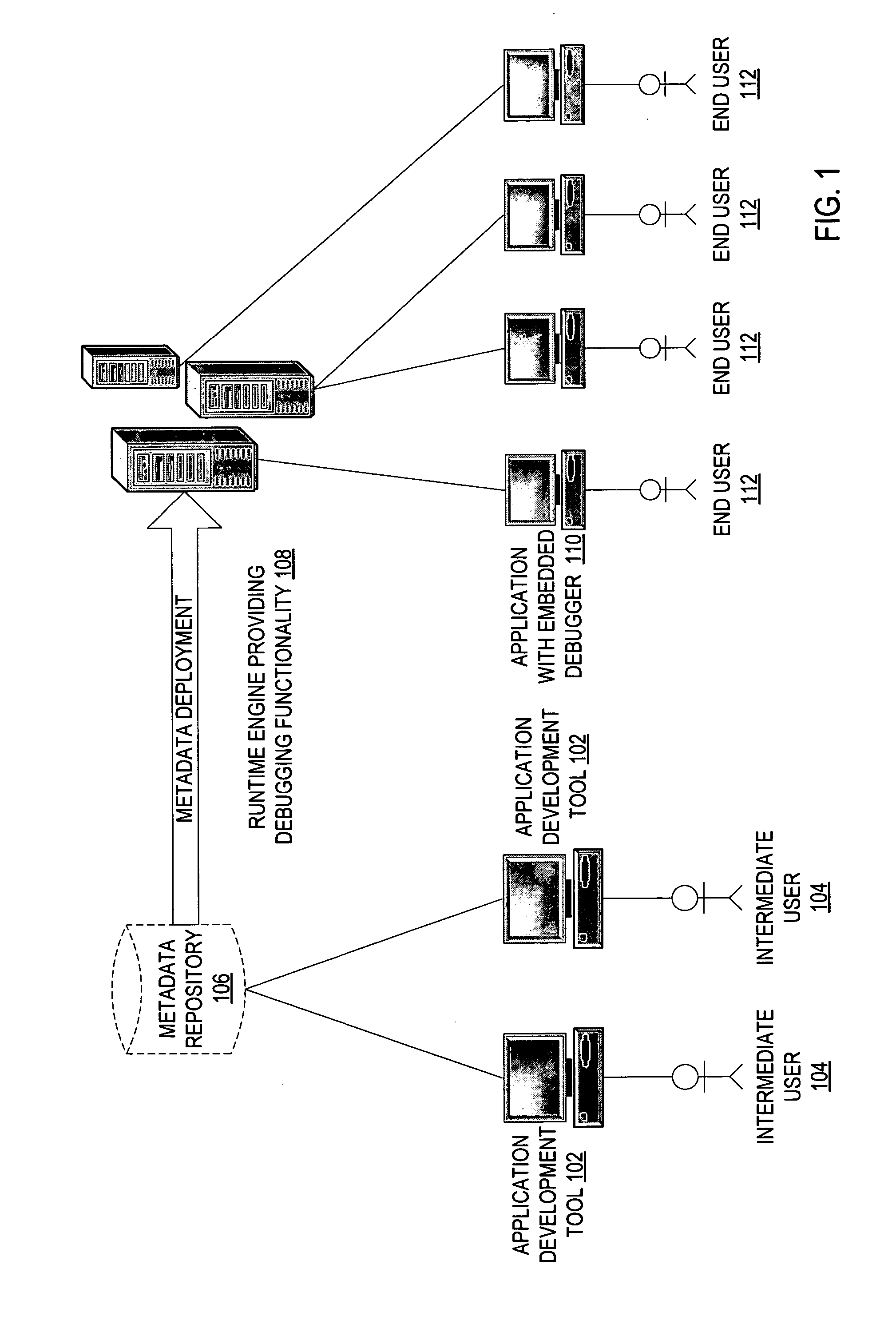
The present invention provides a way to add debugging functionality to an application that supports an n-tiered architecture. This involves showing the user state information at each break point in the production environment. The technical effect of this invention is to make it easier for users to identify and fix issues with the application.

Problems solved by technology

A significant limitation of existing debuggers is that software running under a debugger typically behaves differently than software running normally, because a debugger changes the internal timing of a software program.
That makes it often very difficult to track down runtime problems in complex multi-threaded or distributed systems.
The problem with this approach is that it requires the user to keep the two windows open and in-sync during the entire debugging process.
However, this makes tracking debugging problems occurring in the production environment more difficult.
In addition, design-time debuggers usually connect to the runtime engine, and have the problem of synchronized display of the debugger and end-user user interfaces.

Method used


Image

  • Debugging functionality embedded in an application
  • Debugging functionality embedded in an application
  • Debugging functionality embedded in an application

Examples


Embodiment Construction

[0021] In the following description, numerous details are set forth. It will be apparent, however, to one skilled in the art, that the present invention may be practiced without these specific details. In some instances, well-known structures and devices are shown in block diagram form, rather than in detail, in order to avoid obscuring the present invention.

[0022] Some portions of the detailed descriptions which follow are presented in terms of algorithms and symbolic representations of operations on data bits within a computer memory. These algorithmic descriptions and representations are the means used by those skilled in the data processing arts to most effectively convey the substance of their work to others skilled in the art. An algorithm is here, and generally, conceived to be a self-consistent sequence of steps leading to a desired result. The steps are those requiring physical manipulations of physical quantities. Usually, though not necessarily, these quantities take the...


PUM


Abstract

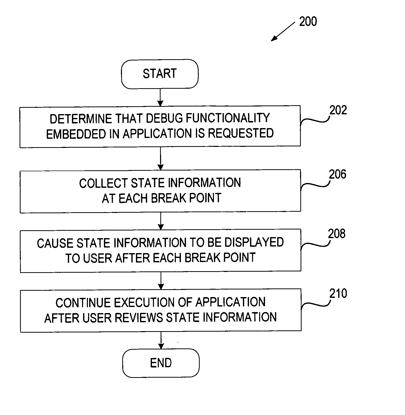
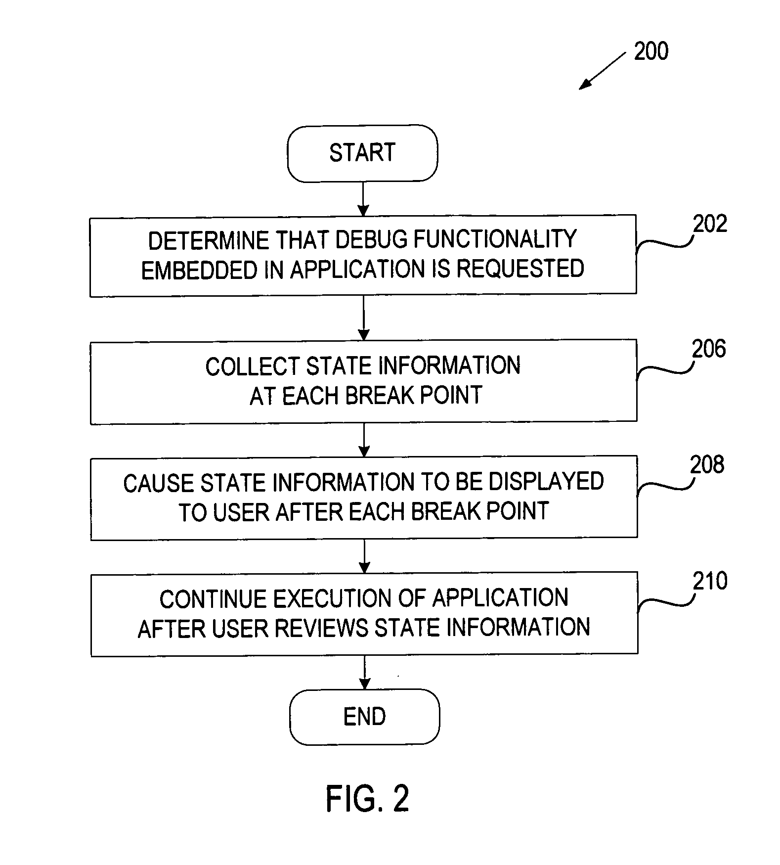
In one embodiment, a method for providing a debugging functionality embedded in an application supporting an n-tiered architecture includes determining that the debugging functionality embedded in the application is requested, and causing current state information to be presented to a user at each break point in the production environment.

Description

RELATED APPLICATIONS [0001] The present application claims priority to U.S. Provisional Applications Ser. Nos. 60 / 727,248 and 60 / 726,871, both filed Oct. 14, 2005, which are incorporated herein in their entirety.FIELD OF THE INVENTION [0002] Embodiments of the present invention relate generally to data processing, and more particularly to providing debugging functionality embedded in an application. COPYRIGHT NOTICE / PERMISSION [0003] A portion of the disclosure of this patent document contains material which is subject to copyright protection. The copyright owner has no objection to the facsimile reproduction by anyone of the patent document or the patent disclosure as it appears in the Patent and Trademark Office patent file or records, but otherwise reserves all copyright rights whatsoever. The following notice applies to the software and data as described below and in the drawings hereto: Copyright © 2006, Oracle Corp., All Rights Reserved. BACKGROUND OF THE INVENTION [0004] A de...

Claims


Application Information

Patent Timeline
Patent Type & Authority Applications(United States)
IPC IPC(8): G06F9/44
CPCG06F11/3632G06F11/30G06F11/3644
Inventor DEGENHARDT, JON REXFORDKAKI, SUDHAKARKAVAL, MARIA ELISABETHTANG, SINFANTULAC, SANJINYASEEN, RAHIM MOHAMED
Owner ORACLE CORPORATION
Learn More