
Opening/closing device for document pressing device

a document pressing and opening/closing technology, which is applied in the direction of door/window fittings, multi-purpose tools, construction, etc., can solve problems such as problems in reading out documents, and achieve the effect of preventing abnormal nois

Inactive Publication Date: 2007-10-18
NISHIDA YUKIHIRO
View PDF9 Cites 10 Cited by
  • Summary
  • Abstract
  • Description
  • Claims
  • Application Information

AI Technical Summary

Benefits of technology

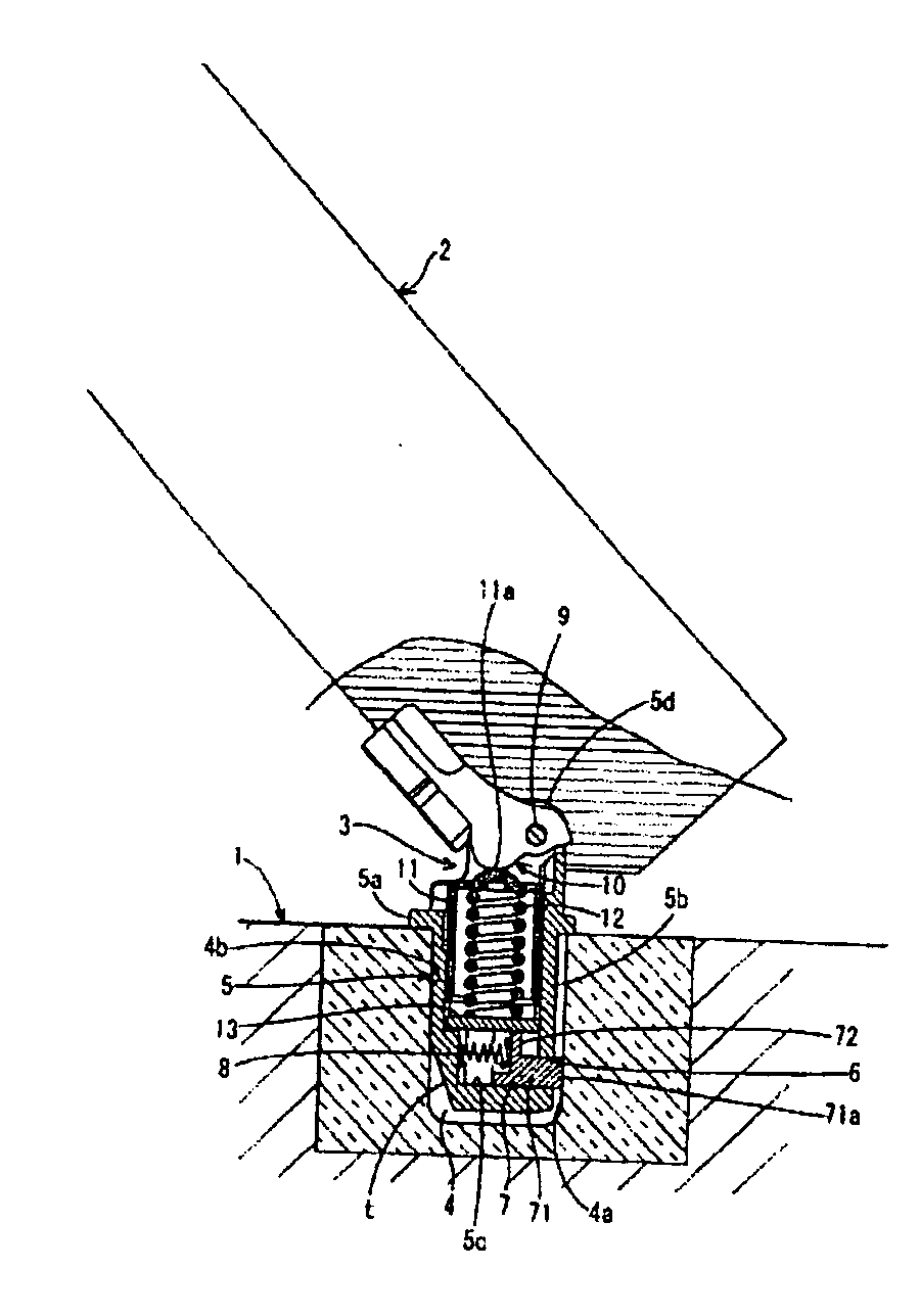
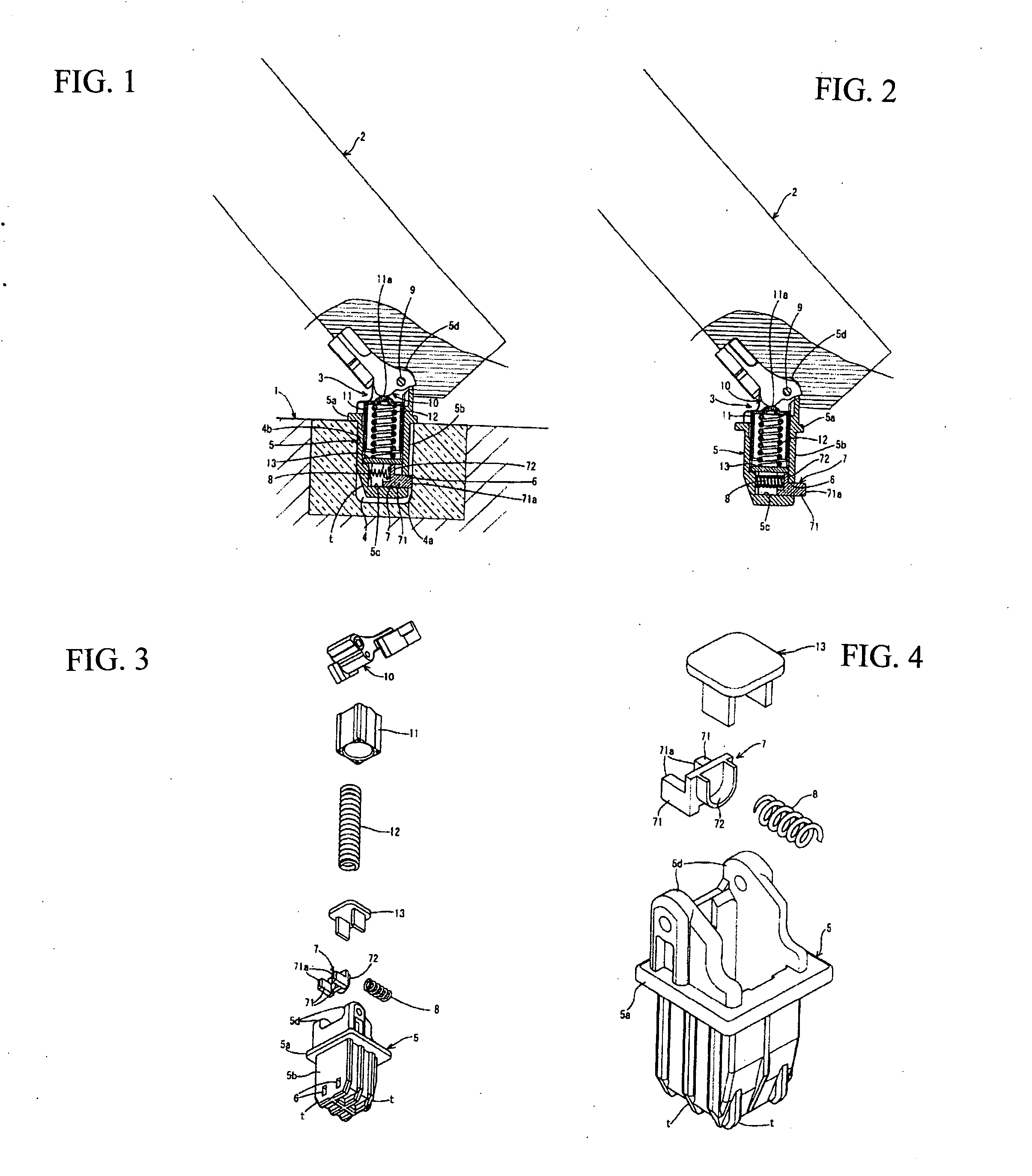
[0010] Thus, allowing the projection member in the tubular supporting leg to freely appear and disappear in the opening part and allowing the projection member to be pressed and biased by a spring member for biasing the projection member so that the tip of the projection member is attached to the inner surface, due to the reaction force of the attachment, the tubular supporting leg is brought to an inner surface that is opposite to the above mentioned inner surface and is fixed so that the supporting leg is not moved in the supporting hole. The tubular supporting leg can be easily inserted into the supporting hole by immersing the tip of the projection member into the opening part resisting the bias of the spring member for biasing the projection member.
[0012] According to the present invention, the tubular supporting leg of the hinge member is securely fixed without jouncing in the supporting hole thanks to the projection member and the spring member for biasing the projection member, preventing abnormal noises from occurring between the tubular supporting leg and the supporting hole when open / close the document pressing plate. Moreover, the hinge member and the document pressing plate can be prevented from being pulled up when the document pressing plate is closed, ensuring the reading out of the document.

Problems solved by technology

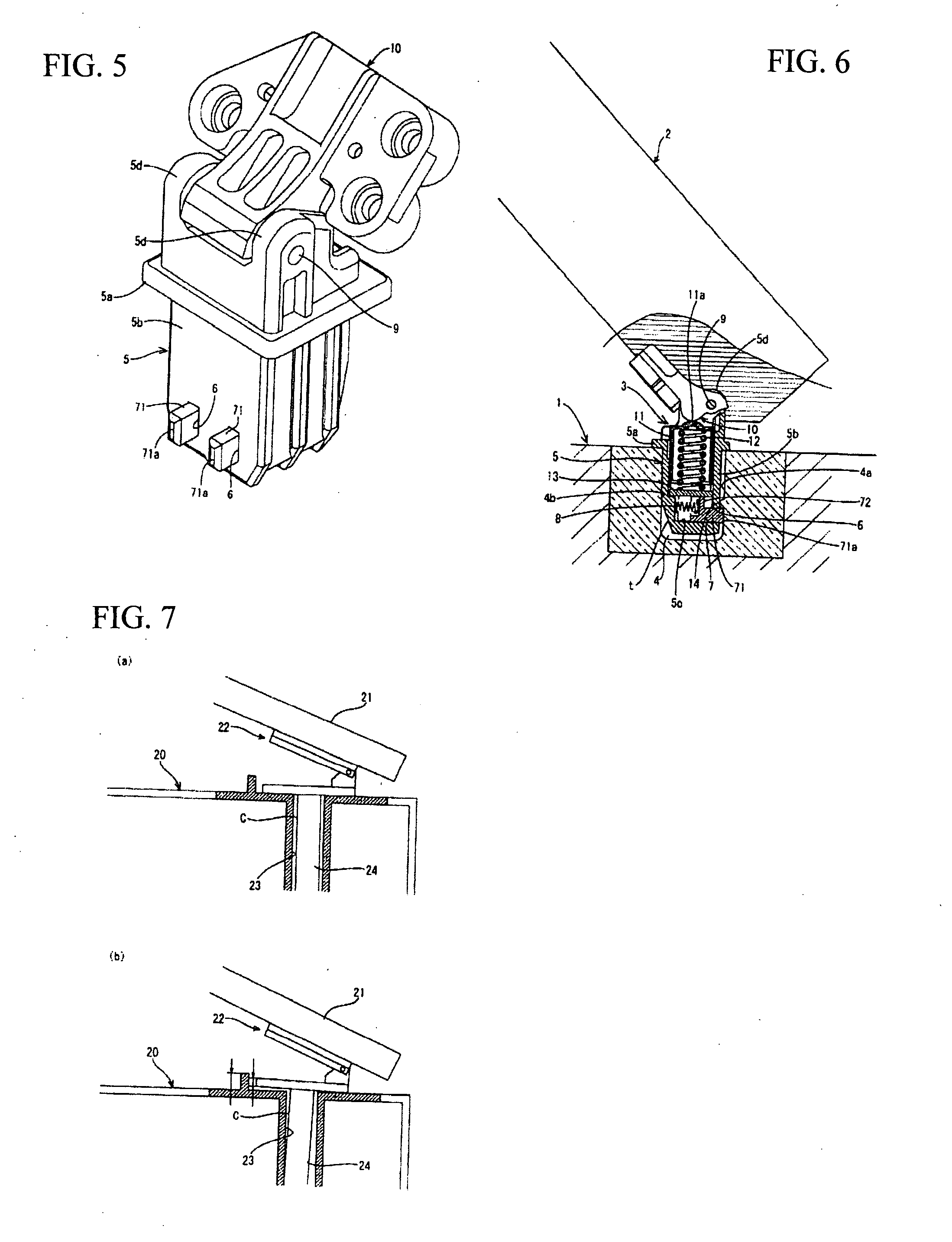
Moreover, when a document placed on the apparatus body 20 is pressed by closing the document pressing plate 21, due to the reaction of the pressing force, the supporting leg 24 is pulled up from the supporting hole 23, causing uneven pressing of the document by the document pressing plate 21, resulting in problems in reading out the document.

Method used


Image

  • Opening/closing device for document pressing device
  • Opening/closing device for document pressing device
  • Opening/closing device for document pressing device

Examples


Embodiment Construction

[0020] A preferred embodiment of the present invention will be described with reference to the figures. FIGS. 1 to 5 show an embodiment example of the present invention. FIG. 1 is a cross-sectional view of an opening / closing device of a document pressing plate in a condition where the document pressing plate is stopped with an opening angle of an intermediate position, FIG. 2 is a cross-sectional view of the same in a condition where a hinge member is fixed to the document pressing plate, FIG. 3 is an exploded perspective view of the hinge member, FIG. 4 is a perspective view of a tubular supporting leg, a projection member, a spring member, and a spring receipt plate of the hinge member seen from a different direction, and FIG. 5 is a perspective view of the hinge member after composition.

[0021] In FIG. 1, the opening / closing device for a document pressing plate of the present invention enables a document pressing plate 2 to be attached on a document placement surface of an appara...


PUM


Abstract

A hinge member 3 that is attached to a document pressing plate 2 and includes a tubular supporting leg 5, in which a projection member 7 is incorporated so that a tip 71a of the projection member 7 appears and disappears in an opening part 6, and a spring member 8 for always biasing the projection member so that the tip 71a of the projection member 7 projects from the opening part 6 is also incorporated. Thus, by attaching the tip 71a that projects from the opening part 6 of the projection member 7 to an inner wall surface 4a of the supporting hole 4, the tubular supporting leg 5 of the hinge member 3 can be securely fixed in the supporting hole 4 without jouncing.

Description

BACKGROUND OF THE INVENTION [0001] 1. Field of the Invention [0002] The present invention relates to an opening / closing device for a document pressing plate of a copier, a printer, a scanner, or the like. [0003] 2. Description of the Related Art [0004] Conventionally, as an opening / closing device for this kind of document pressing plate, there has been known an image scanning apparatus body 20 (hereinafter referred to as the apparatus body) of which document opening / closing plate 21 is attached to the device body via a hinge member 22, as shown in FIG. 7, so that the plate can be opened and closed in a rotational manner (for example, refer to the Patent Document 1). [0005] The hinge member 22 is attached on the edge side of a rotator and is equipped with a supporting leg 24 that is inserted into a supporting hole 23 provided on an upper surface of the apparatus body 20. As shown in FIG. 7 (a), the hinge member 22 attached to the document pressing plate 21 is fixed on the apparatus b...

Claims


Application Information

Patent Timeline
Patent Type & Authority Applications(United States)
IPC IPC(8): E05D7/00
CPCE05D7/12E05D2007/128Y10T16/522E05Y2600/53E05Y2900/606E05Y2201/222E05Y2999/00
Inventor NISHIDA, YUKIHIRO
Owner NISHIDA YUKIHIRO
Learn More