
Air Bag Deployment Ramp

a technology for air bags and ramps, which is applied in the direction of pedestrian/occupant safety arrangements, vehicular safety arrangments, vehicle components, etc., can solve the problems of affecting the speed and direction of inflation, bag rips, trim panels may be fractured and/or detached, etc., to facilitate the emergence, direction and/or placement of inflating

Inactive Publication Date: 2007-10-18
COLLINS & AIKMAN PROD CO
View PDF33 Cites 18 Cited by
  • Summary
  • Abstract
  • Description
  • Claims
  • Application Information

AI Technical Summary

Benefits of technology

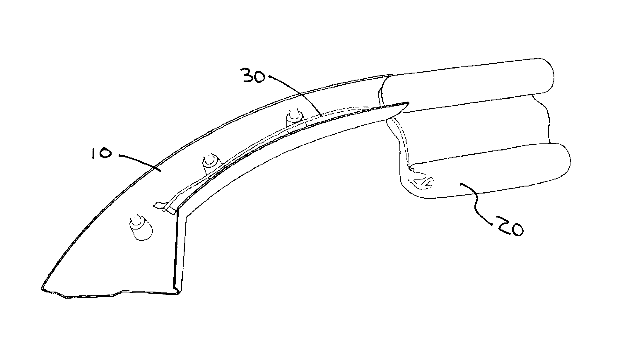
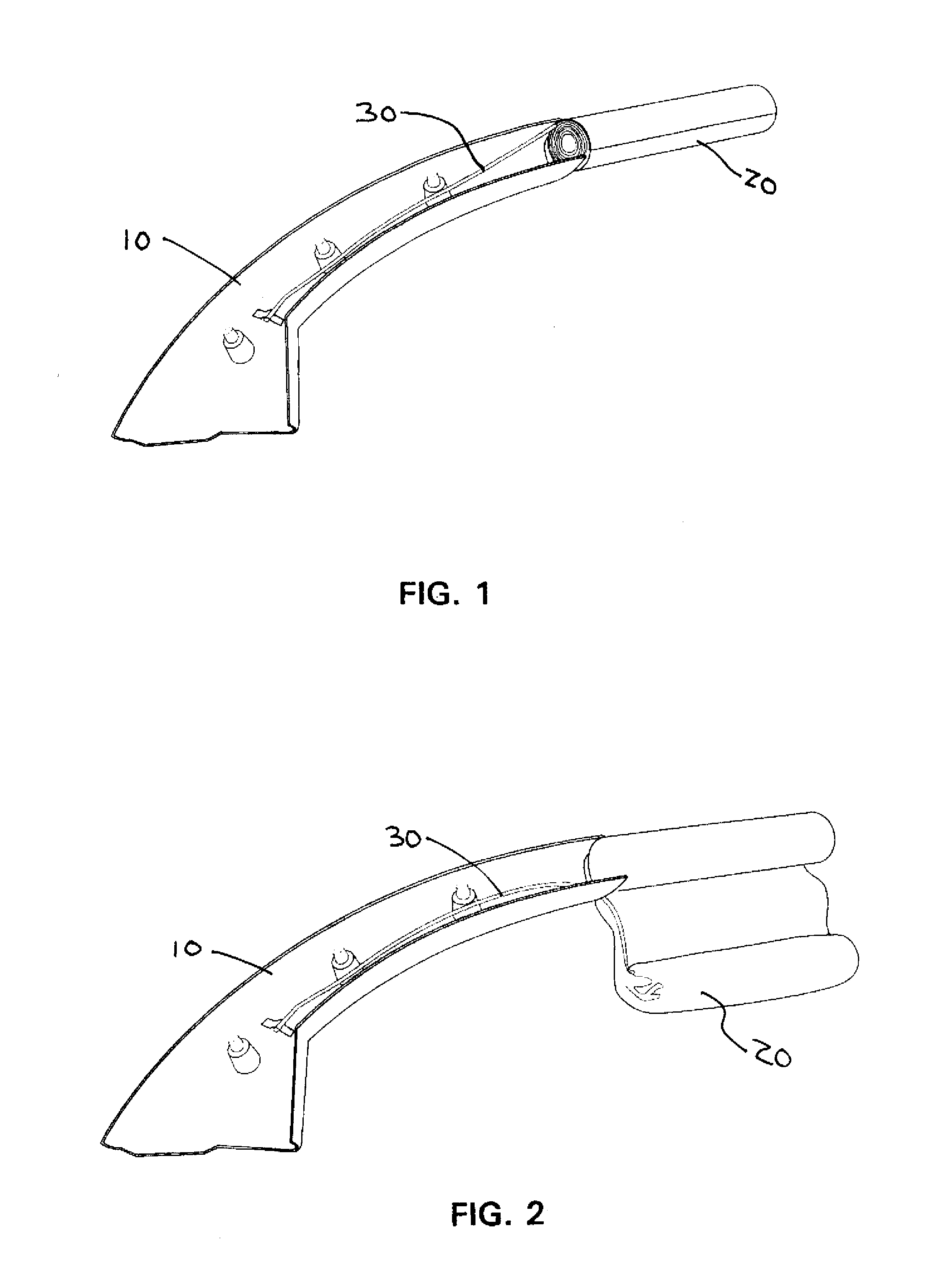
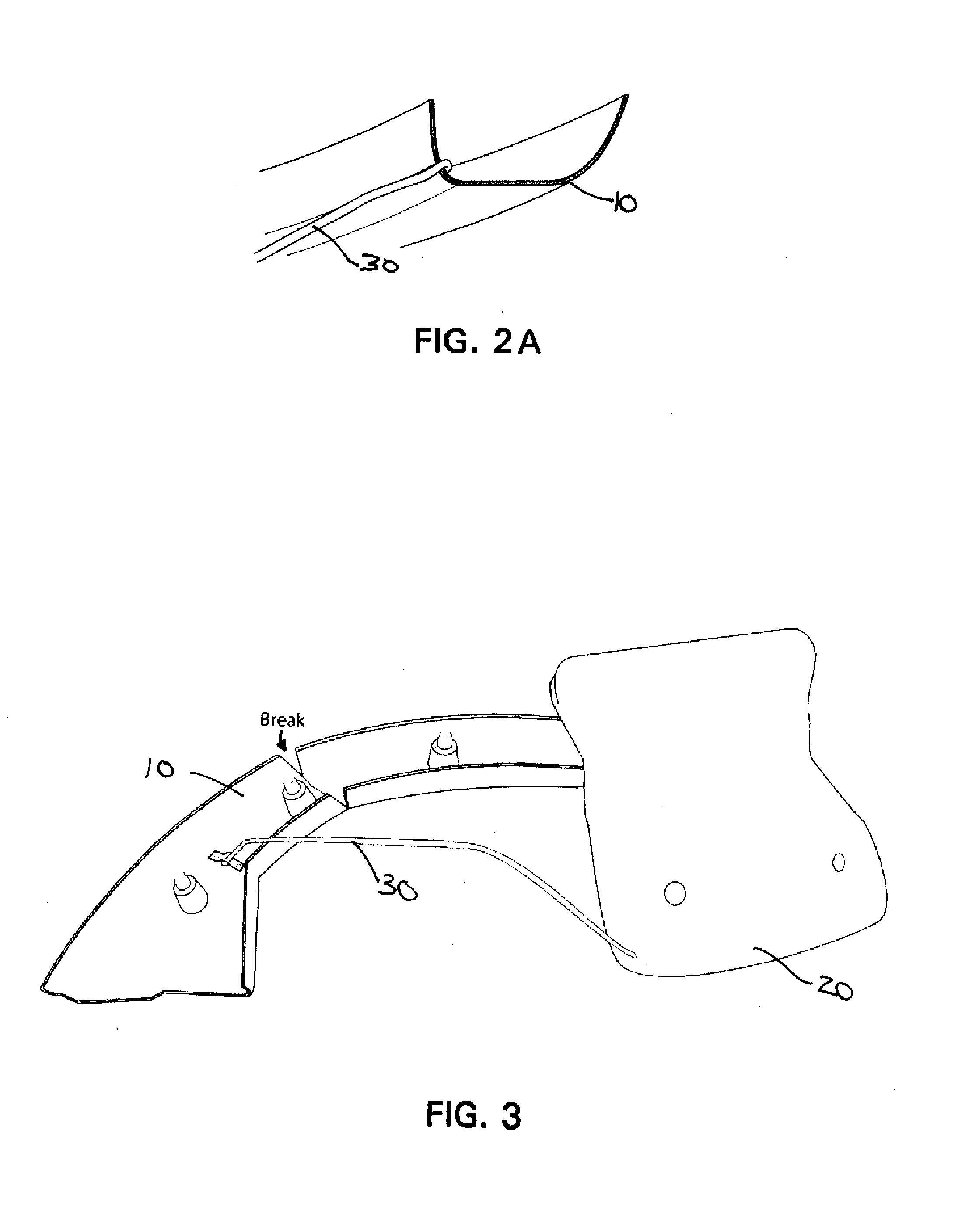
[0012] In another exemplary embodiment, the present invention relates to a deployment ramp for guiding the emergence of an inflating air bag from behind a trim panel that may be integrally formed to extend from a surface of the trim panel. This integrally formed member, which may be in the form of one or more rib-like projections or protrusions, may include a fold line to allow the projection to be folded towards the surface of the panel. The shape thus formed may act as a deployment directing ramp to facilitate the emergence, direction and / or placement of the inflating air bag as it emerges from behind the panel.

Problems solved by technology

Any unplanned resistance applied to the inflating bag by the overlying panels may affect the speed and direction of inflation.
If the bag should become caught on a trim panel, the bag may become ripped or the trim panel may be fractured and / or detached and launch into the occupant compartment.
In addition, the strap or tether that aids in directing the air bag may become caught on an edge of an adjacent trim panel.

Method used


Image

  • Air Bag Deployment Ramp
  • Air Bag Deployment Ramp
  • Air Bag Deployment Ramp

Examples


Embodiment Construction

[0030] The present invention is described more fully hereinafter with reference to the accompanying drawings, in which preferred embodiments of the invention are shown. This invention, may, however, be embodied in many different forms and should not be construed as limited to the embodiments set forth herein; rather, these embodiments are provided so that this disclosure will be thorough and complete, and will fully convey the scope of the invention to those skilled in the art.

[0031] For elements common to the various embodiments of the invention, the numerical reference character between the embodiments is held constant, but distinguished by the addition of an alphanumeric character to the existing numerical reference character. In other words, for example, an element referenced at 10 in the first embodiment is correspondingly references at 10A, 10B, and so forth in subsequent embodiments. Thus, where an embodiment description uses a reference character to refer to an element, the...


PUM


Abstract

A ramp for directing the deployment of an expanding air bag may be formed to extend from a surface of a trim panel. The ramp may comprise one or more projections having a hinge or fold line. After molding of the trim panel, the projection may be folded along the hinge line towards the surface of the panel to form a ramp structure to promote the emergence, direction and / or placement of an expanding air bag. The ramp structure may be formed on any surface of trim panels lying adjacent or over an air bag system.

Description

FIELD OF THE INVENTION [0001] The present invention relates to inflatable air bags used in vehicles to protect occupants in the event of a crash, and more particularly, to a ramp that may be used to direct the path of a deploying air bag. BACKGROUND OF THE INVENTION [0002] Currently, a number of inflatable air bag systems are provided in motor vehicles to cushion the occupant in the event of a crash. These air bags may typically deploy from behind molded trim panels in the steering wheel, instrument panel, seat, door panel, side trim or headliner areas of the vehicle. The air bags may be designed to inflate based on sensors which detect a sudden deceleration or change in direction of the vehicle and cushion the occupants from directly impacting hard surfaces, thus preventing injury or even death. [0003] The air bag system typically may include one or more sensors, an inflator, an inflatable air bag and a trim panel which may hide the bag from view and aesthetically blend into the in...

Claims


Application Information

Patent Timeline
IPC IPC(8): B60R21/213B60R21/215
CPCB60R13/02B60R13/0243B60R13/025B60R2021/161B60R13/0275B60R21/215B60R2013/0287B60R13/0256
Inventor WALLACE, MARK
Owner COLLINS & AIKMAN PROD CO
Learn More