In Situ Photoluminescence Characterization System and Method

Inactive Publication Date: 2012-12-27
MELONI MARK ANTHONY
View PDF2 Cites 33 Cited by
  • Summary
  • Abstract
  • Description
  • Claims
  • Application Information

AI Technical Summary

Benefits of technology

[0011]Light wavelengths corresponding to, at least, the wavelengths of the photoluminescence emission region are filtered from the wide spectrum of light using an optical filter commonly named a notch or minus filter. Additionally or alternatively, the filtered band does not extend into wavelengths corresponding to the region of wavelengths with encoded information. In so doing, light generated by a single broadband light source can both excite emissions from the workpiece that can be measured and simultaneously illuminate the workpiece across the region of wavelengths useful for encoding information from the workpiece, the reflected light from which can also

Problems solved by technology

Yield loss in LEDs may arise in the forms of low output, decreased lifetime, shifted wavelength output and other properties.
With a long delay between LED wafer fabrication and L

Method used


Image

  • In Situ Photoluminescence Characterization System and Method
  • In Situ Photoluminescence Characterization System and Method
  • In Situ Photoluminescence Characterization System and Method

Examples


Example

[0031]Other features of the present invention will be apparent from the accompanying drawings and from the following detailed description.

DETAILED DESCRIPTION OF THE INVENTION

Element Reference Number Designations

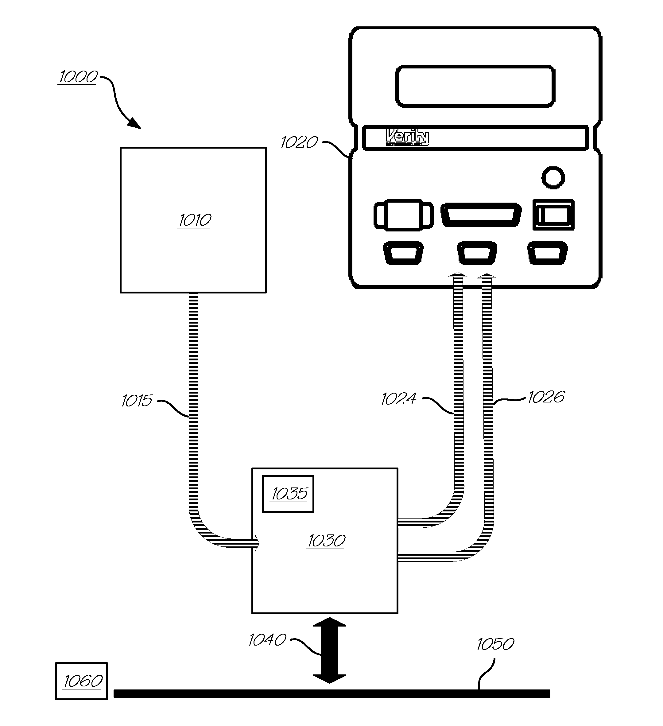
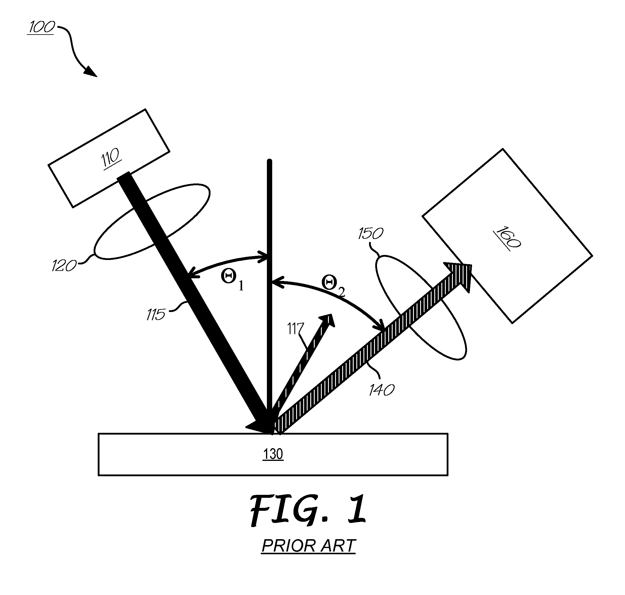
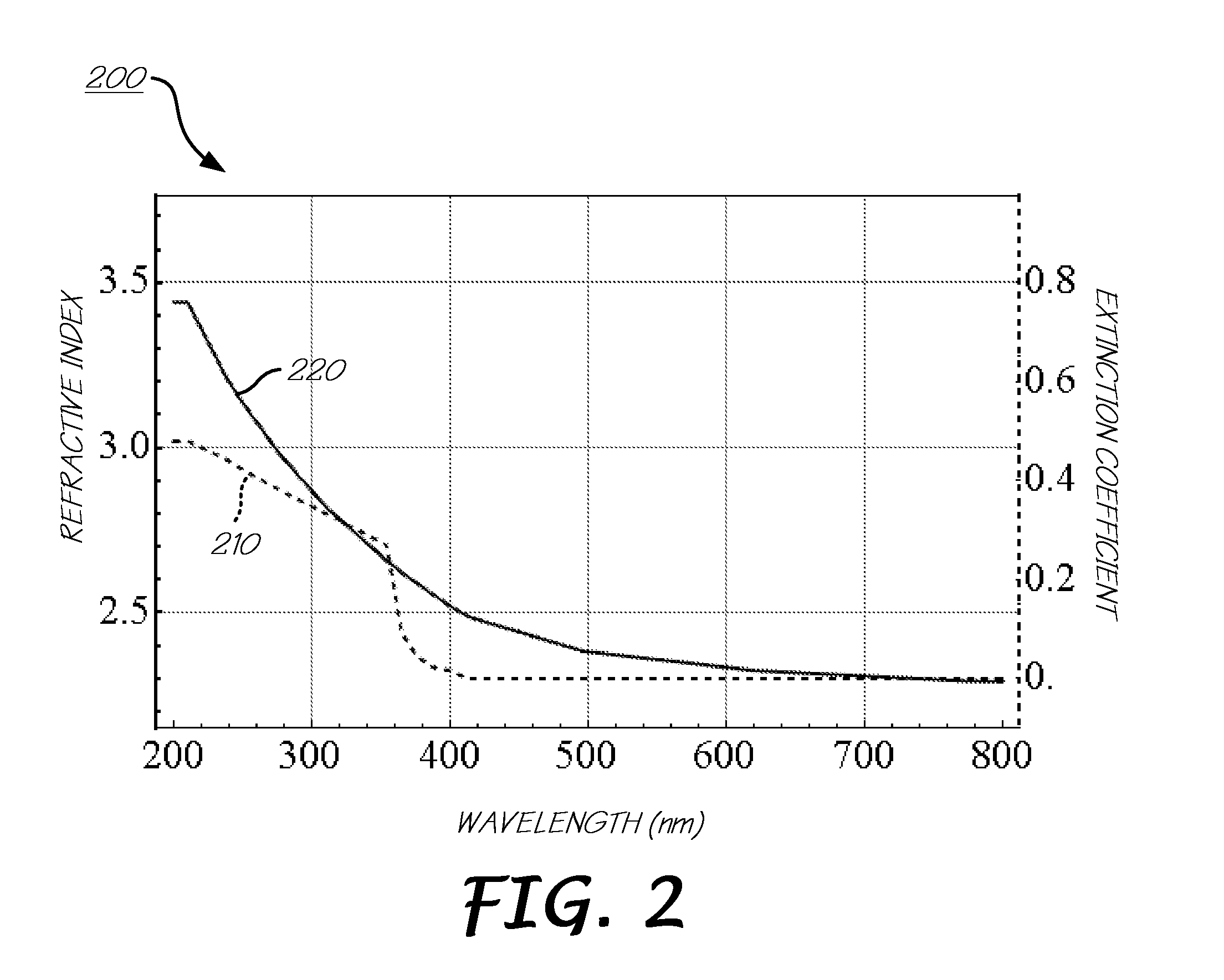
[0032]100: Workpiece characterization system[0033]110: Excitation source[0034]115: Light[0035]117: Specularly reflected excitation light[0036]120: Optics[0037]130: Workpiece[0038]140: Photoluminescence emission light[0039]150: Optics[0040]160: Light analyzing device[0041]200: Plot of the refractive index and extinction coefficient vs. wavelength for GaN[0042]210: Extinction coefficient vs. wavelength[0043]220: Refractive index vs. wavelength[0044]300: Plot of the reflectance vs. wavelength for GaN[0045]310: Reflectance vs. wavelength[0046]400: Plot of the typical photoluminescence emission curve for GaN[0047]410: Modulated photoluminescence emission vs. wavelength[0048]415: Unmodulated photoluminescence emission vs. wavelength[0049]420: High absorption wavelength region[0050...


PUM


Abstract

A workpiece characterization system for measurement of photoluminescence and/or layer properties of a workpiece. The workpiece characterization system includes an excitation light impinging upon a surface of a workpiece whereby the workpiece emits photoluminescent light. The emitted photoluminescent light may be characterized and correlated for determination of workpiece parameters such as dopant concentrations and LED performance characteristics. Additionally, the workpiece characterization system may also include an illumination impinging upon a surface of said workpiece whereby the illumination source is encoded with layer information from said workpiece. One or both of the lights are selectively collected, and each collected light is angularly and spatially sampled. Layer properties and/or photoluminescence properties of said workpiece may be measured from the selectively collected, and angularly and spatially sampled lights.

Description

CROSS-REFERENCE TO RELATED APPLICATIONS[0001]This application is a continuation in part, related to and claims the benefit of priority to US patent application Ser. No. 13 / 166,571, filed Jun. 22, 2011, entitled “Workpiece Characterization System,” currently pending and which is assigned to the assignee of the present invention. This application is related to US patent application Ser. No. 13 / 286,050, filed Oct. 11, 2011, entitled “Workpiece Characterization System,” currently pending and which is assigned to the assignee of the present invention. The above identified applications are incorporated by reference herein in their entireties.BACKGROUND OF THE INVENTION[0002]The present invention relates generally to workpiece characterization systems and methods of use. More particularly, the present invention relates to a system, method and software program product for obtaining simultaneous measurement of layer and photoluminescence properties of light emitting diodes using a wide spect...

Claims


Application Information

Patent Timeline
IPC IPC(8): G01N21/64
CPCG01N21/6489G01N2021/6421G01N2021/6419
Inventor MELONI, MARK ANTHONY
Owner MELONI MARK ANTHONY
Why Eureka
Try Eureka