
Press die, drawing method, and pressed product

Inactive Publication Date: 2007-10-25
FUJIFILM CORP
View PDF4 Cites 2 Cited by
  • Summary
  • Abstract
  • Description
  • Claims
  • Application Information

AI Technical Summary

Benefits of technology

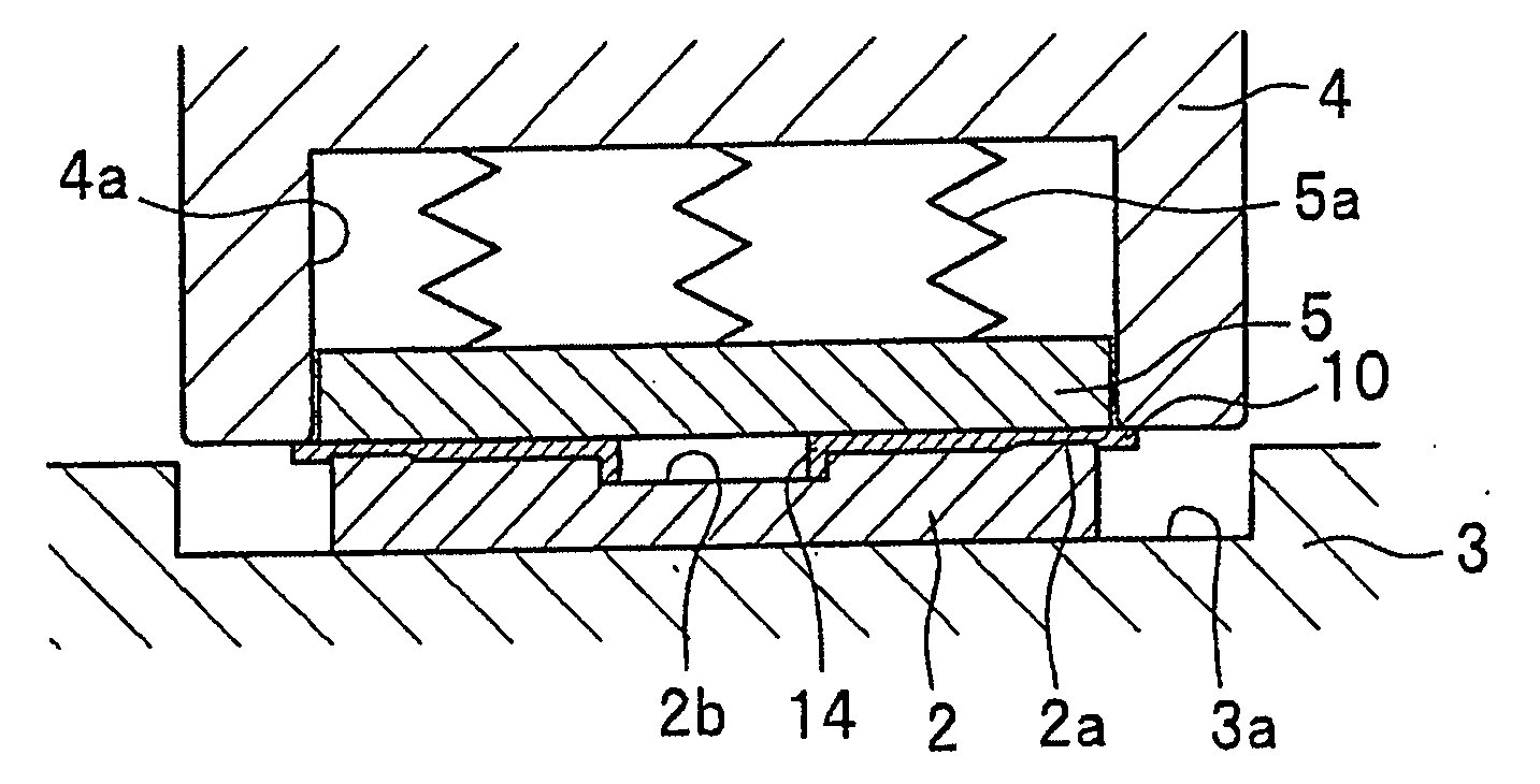
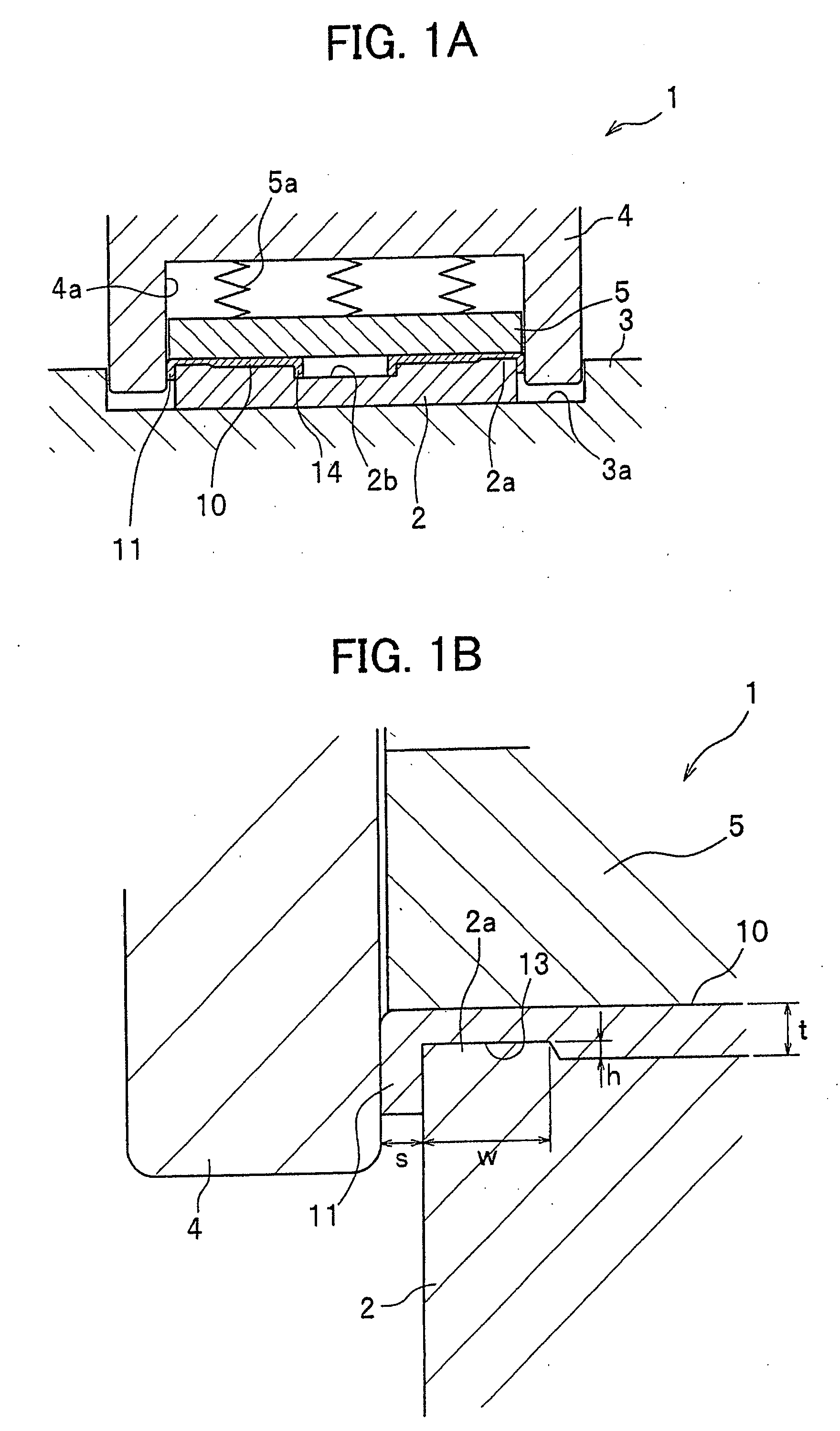
[0015]Such press die allows the peripheral edge wall to be molded while the material (peripheral edge of the workpiece) is compressed because the clearance between the die and the punch is in the range of not less than 70% and not more than 95% of the thickness of the workpiece before forming. This ensures the peripheral edge wall to be pressed and bent along the peripheral edge of the die from its base, so that the peripheral edge wall is molded in a desired shape. Also, the peripheral edge wall is plastic-deformed at its base, and thereby the occurrence of warpage in a flat portion continuous with the edge wall is suppressed. In addition, in order to suppress the warpage in the flat portion, it is more effective if the clearance between the die and the punch is set in a range of not less than 80% and not more than 95% of the thickness of the workpiece. Note that if the clearance between the die and the punch is less than 70% of the thickness of the workpiece before forming, a defect such as a crack is more likely to occur on the peripheral edge wall, whereas if the clearance is more than 95% of the thickness of the workpiece before forming, a defect such as any of larger warpage and larger deformation in the flat portion is more likely to occur.
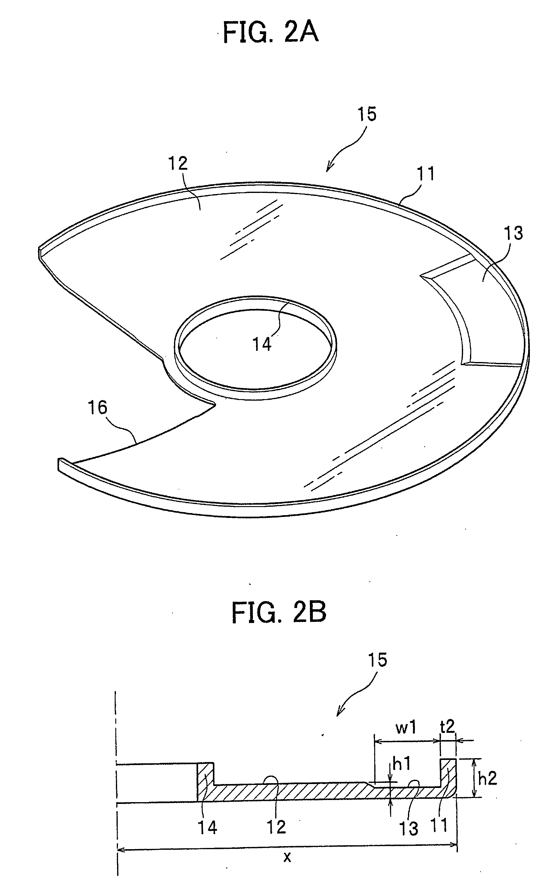
[0017]Regarding a pressed product molded to have a peripheral edge wall, this drawing method allows warpage in a flat portion continuous with the edge wall to be reduced compared with a conventional method, and the pressed product to be molded with good flatness because the clearance between the die and the punch is set in the range of not less than 70% and not more than 95% of the thickness of the workpiece before forming. Furthermore, if the clearance between the die and the punch is set in a range of not less than 80% and not more than 95% of the thickness of the workpiece before forming, the warpage in the flat portion can be more effectively reduced. Note that if the clearance between the die and the punch is less than 70% of the thickness of the workpiece before forming, a defect such as a crack is more likely to occur on the peripheral edge wall, whereas if the clearance is more than 95% of the thickness of the workpiece before forming, a defect such as any of larger warpage and larger deformation in the flat portion is more likely to occur.
[0025]The press die and the drawing method according to the present invention enable warpage occurred in the flat portion continuous with the inside of the peripheral edge wall to be reduced when the wall portion (peripheral edge wall) is molded at the outer peripheral edge by drawing. Also, the pressed product according to the present invention has small warpage and good flatness, so that it can preferably be used as a member of a precision component and the like.

Problems solved by technology

Note that if the clearance between the die and the punch is less than 70% of the thickness of the workpiece before forming, a defect such as a crack is more likely to occur on the peripheral edge wall, whereas if the clearance is more than 95% of the thickness of the workpiece before forming, a defect such as any of larger warpage and larger deformation in the flat portion is more likely to occur.

Method used


Image

  • Press die, drawing method, and pressed product
  • Press die, drawing method, and pressed product
  • Press die, drawing method, and pressed product

Examples


example

[0061]A result of a demonstration experiment regarding an enhancement in quality of the pressed product 15 molded by the press die 1 and the drawing method according to the present invention will be described.

[0062]In this demonstration experiment, drawing was performed under a condition that the clearance s between the die 2 and the punch 4 was varied, and warpage in the flat portion 12 of pressed products was measured to thereby demonstrate the quality enhancement effect (reduction of an amount of the warpage in the flat portion 12) based on the drawing method of using the press die 1 according to the present invention.

[0063]In this demonstration experiment, the metal plate 10 (stainless steel SUS 304-SP) having a thickness of 0.15 mm was used. The state of warpage in the flat portion 12 was measured for and compared with each of two cases where the clearances s between the die 2 and the punch 4 were set to 100% (s=0.15 mm) of the thickness t of the metal plate 10 and 90% (s=0.135...


PUM

PropertyMeasurementUnit
Fractionaaaaaaaaaa
Fractionaaaaaaaaaa
Fractionaaaaaaaaaa

Abstract

A press die for molding an edge wall at a peripheral edge of a workpiece includes a die convexly formed along a shape of one surface of the edge wall, a punch formed with a concave portion along the other surface of the edge wall, and a stripper for holding the workpiece with the die therebetween, wherein a clearance between the die and the punch is in a range of not less than 70% and not more than 95% of a thickness of the workpiece before forming.

Description

BACKGROUND OF THE INVENTION[0001]1. Field of the Invention[0002]The present invention relates to a press die, a drawing method using the press die, and a pressed product molded by the drawing method.[0003]2. Description of the Related Art[0004]In a pressed product in which a peripheral edge wall is molded at a peripheral edge, the edge wall may be molded by drawing.[0005]Drawing is a forming method in which for example, when a peripheral edge wall is molded at a peripheral edge of a workpiece, the peripheral edge of the workpiece is bent while a pressing force is applied to the edge wall portion.[0006]When the peripheral edge of the workpiece is bent, an excess part of the material (redundant part) may occur, causing wrinkles; however, drawing the redundant part while pressing it allows the occurrence of the wrinkles to be prevented.[0007]In such a drawing method, the peripheral edge wall of a uniform thickness is molded by applying the pressing force with a punch to the workpiece p...

Claims


Application Information

Patent Timeline
IPC IPC(8): B21D11/00
CPCB21D22/02
Inventor SHIGA, HIDEAKIMORIWAKI, MASAYOSHI
Owner FUJIFILM CORP
Learn More