Surgical manipulator

a manipulator and surgical technology, applied in the field of manipulators, can solve the problems of surgeons who are used to perform very complex and/or physically demanding surgical procedures, surgeons can easily become fatigued, and surgeons may have to orient their hands in awkward positions, so as to improve the dexterity and precision of surgeons/operators, reduce the likelihood of movement of patients, and enhance patient safety

Inactive Publication Date: 2007-10-25
MICRODEXTERITY SYST
View PDF99 Cites 71 Cited by
  • Summary
  • Abstract
  • Description
  • Claims
  • Application Information

AI Technical Summary

Benefits of technology

The technical effect of this patent is to improve the ability of a surgeon to perform delicate operations with greater accuracy and ease. It also reduces the risk of injury to patients while they are being operated on. Additionally, it helps achieve better alignment between images used for guidance and actual physical structures within the body.

Problems solved by technology

This patent discusses how some complicated surgeries require significant amounts of manual labor from the surgeon, leading to fatigue and reduced accuracy. To address this issue, researchers have developed powered manipulators called robotic arms to help improve the surgeon's ability to handle instruments during these operations. While these machines offer many benefits, they pose their own set of risks due to potential movements of the patient relative to the machine. Therefore, the technical problem addressed in this patent is finding ways to safely utilize powered manipulators while reducing the likelihood of patient injury.

Method used


Image

  • Surgical manipulator
  • Surgical manipulator
  • Surgical manipulator

Examples


Embodiment Construction

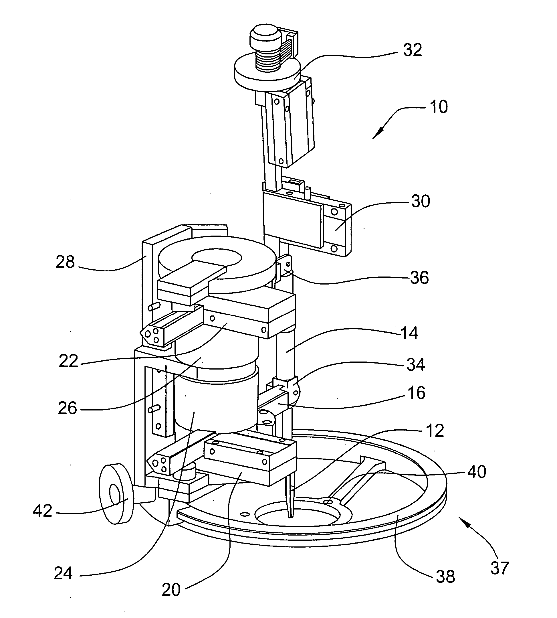
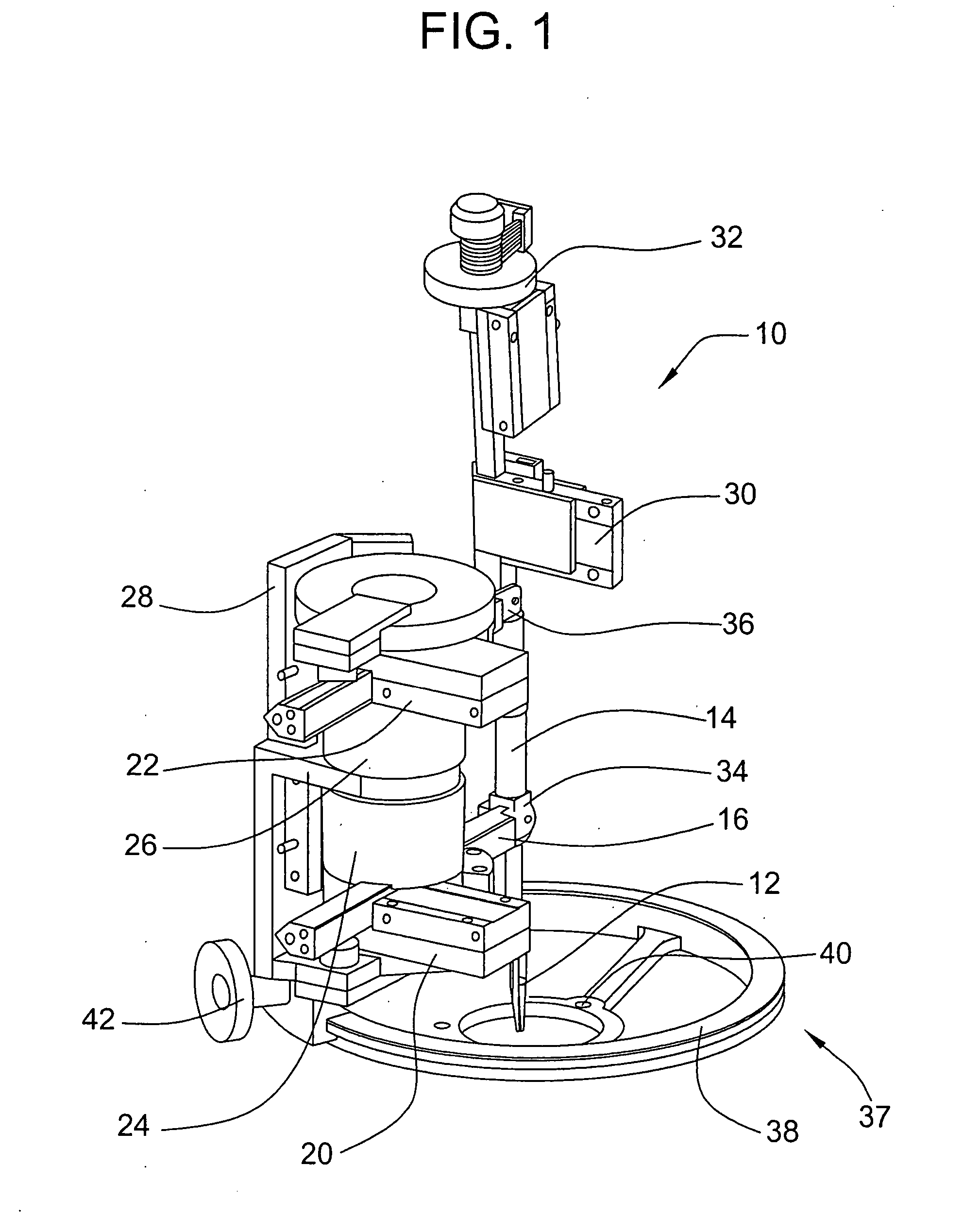
[0021] Referring now more particularly to FIG. 1 of the drawings there is shown an illustrative embodiment of a surgical manipulator 10 constructed in accordance with the present invention. The illustrated manipulator 10 can interchangeably support and move a medical tool 12 with up to six degrees of freedom. As will be appreciated, the invention is not limited to any particular type of medical tool rather any suitable tool can be used with the manipulator including, but not limited to, needle holders, staple or clamp appliers, probes, scissors, forceps, cautery, suction cutters, dissectors, drills, lasers, ultrasonic devices and diagnostic devices. The tools can be reusable, limited reuse or disposable. If the medical tool has moving parts that are conventionally human powered, the manipulator 10 can be adapted to accommodate an actuator dedicated to powering the tool such as for example an electric, pneumatic or hydraulic actuator.

[0022] In order to provide dexterity enhancement ...


PUM


Abstract

The present invention provides a surgical manipulator which is capable of manipulating a surgical or medical tool in up to six degrees of freedom. The manipulator has a haptic interface and an associated position sensing system. A controller is provided that can be used to adjust movement information from the haptic interface based on the relative orientations of the manipulator and the haptic interface.

Description


Claims


Application Information

Patent Timeline
Owner MICRODEXTERITY SYST
Why Eureka
Try Eureka