
Temporary well zone isolation

a well zone and tunnel technology, applied in the field of oilfield tools, can solve the problems of reducing the application range of the plug, limiting the application range of the substantially horizontal well, and reducing the use of the plug, so as to facilitate the rupture of the frangible barrier elemen

Inactive Publication Date: 2007-11-01
WEATHERFORD TECH HLDG LLC
View PDF23 Cites 36 Cited by
  • Summary
  • Abstract
  • Description
  • Claims
  • Application Information

AI Technical Summary

Benefits of technology

[0009] The temporary well isolation device also has frangible barrier element within the housing, where the frangible barrier element is sealingly engaged in the passage blocking fluid flow through the passage. The frangible barrier element bears a load from fluid pressure. The temporary well isolation device also has a disengagable constraint in contact with the frangible barrier element so as to redirect the load on the frangible barrier element from a first component of the load to a second component of the load, thereby preventing rupture of the frangible barrier element.
[0011] Also disclosed herein is a method for disintegrating a frangible barrier element disposed in a passage of a temporary well isolation device where the frangible barrier element blocks fluid flow through the passage and thereby supports a load from fluid pressure. The method includes facilitating rupture of the frangible barrier element from a first component of the load by structurally increasing the ratio of the first component of the load to a second component of the load. In some embodiments, the method may also include increasing the fluid pressure above the frangible barrier element. In some embodiments, the first component of the load is the compressive component and the second component of the load is the tensile component. Structurally increasing the ratio of the first component of the load to the second component of the load further may include disengaging a constraint.

Problems solved by technology

Designs relying on gravity for removal of the plug, however, have limited applications in substantially horizontal wells.
The aforementioned disappearing plugs currently in use, while an improvement over previous technology, are less than ideal because they lack reliability, especially in environments where wells deviate from vertical.

Method used


Image

  • Temporary well zone isolation
  • Temporary well zone isolation
  • Temporary well zone isolation

Examples


Embodiment Construction

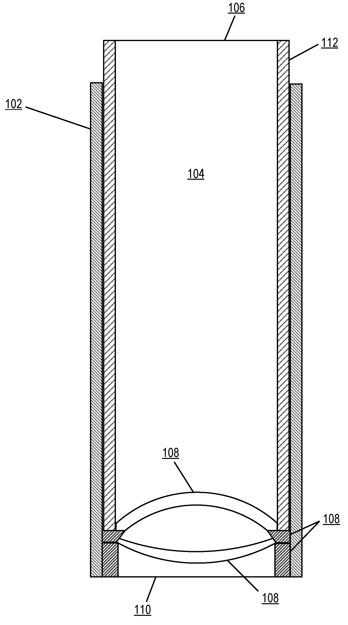
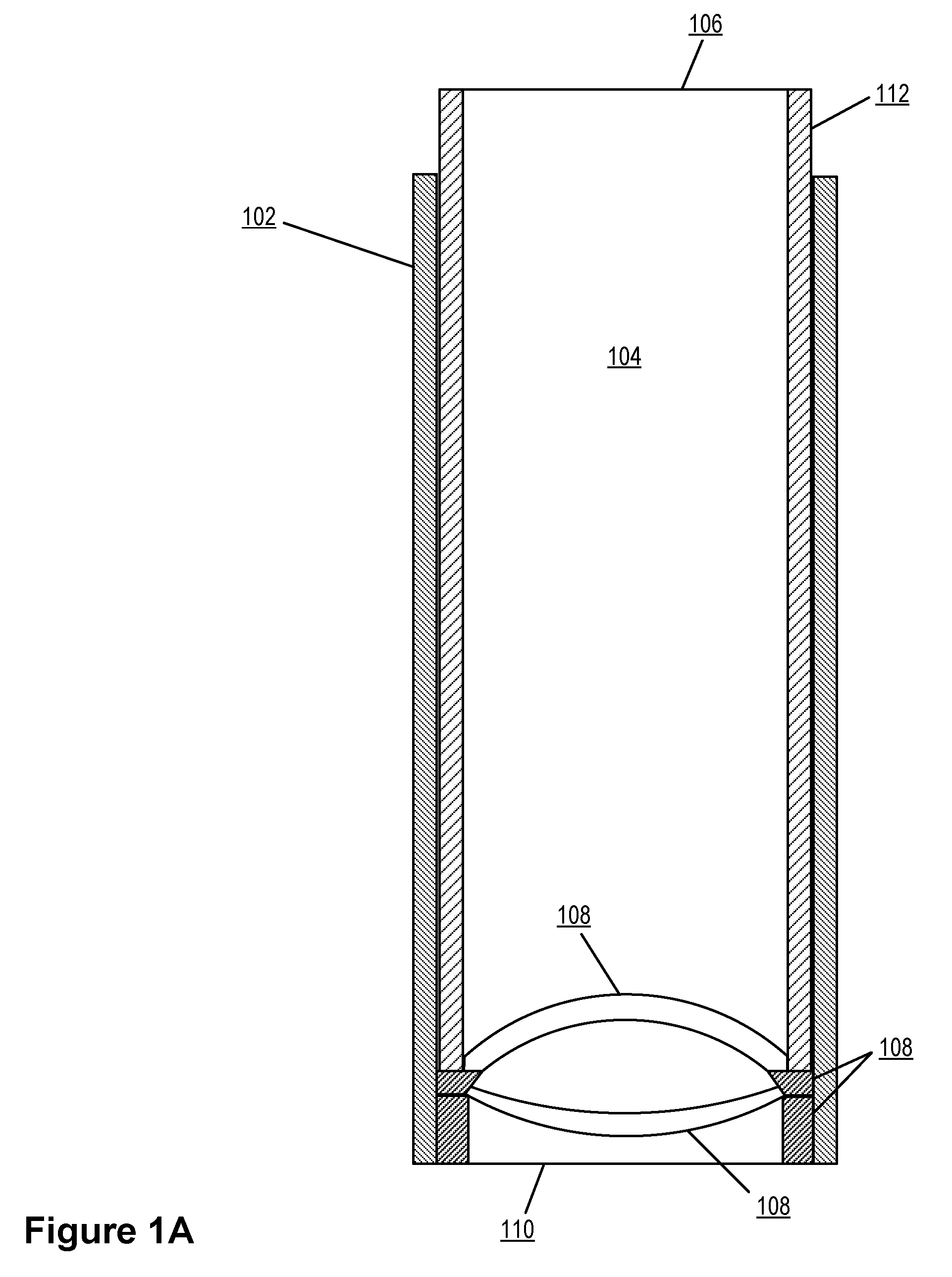
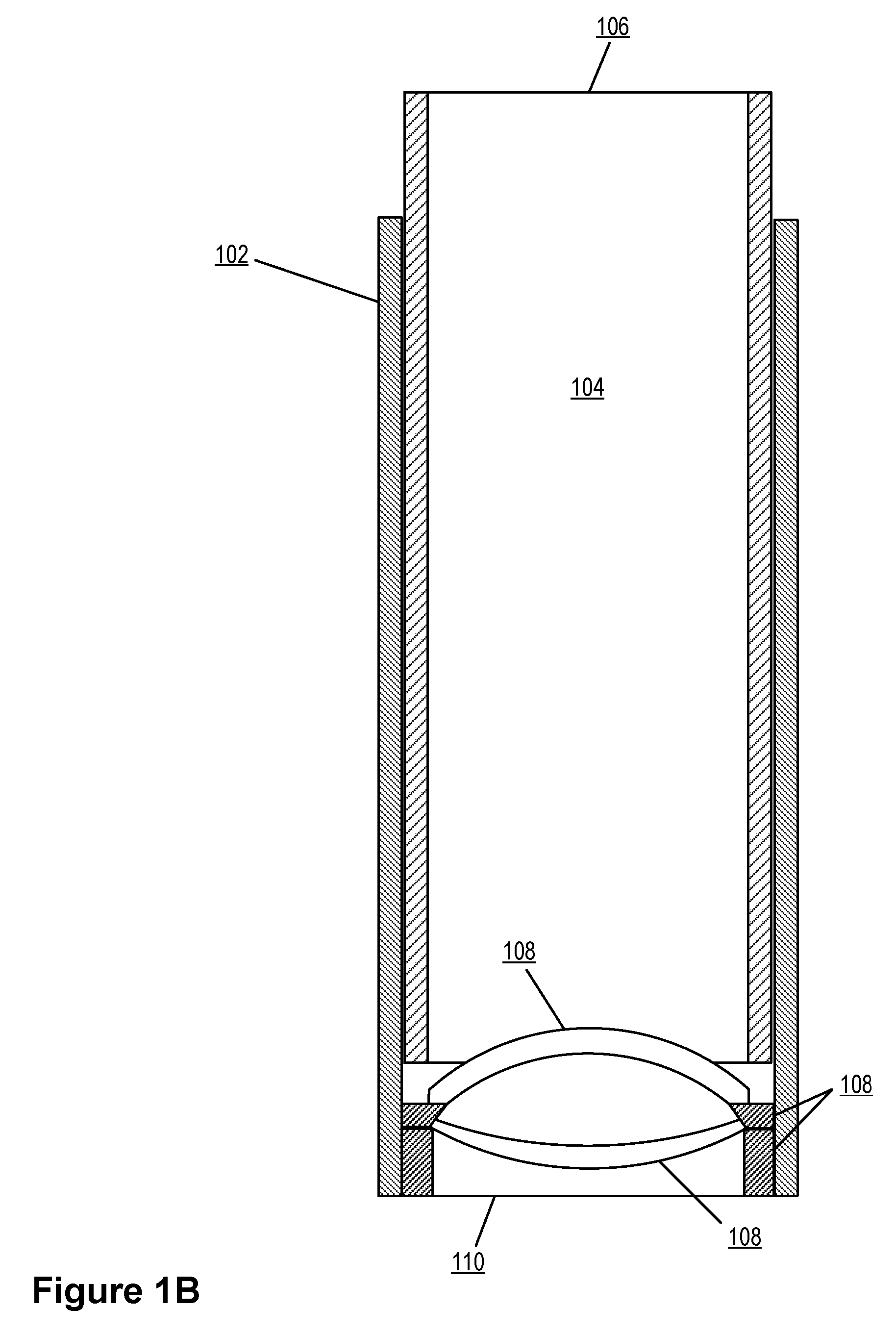
[0019] Exemplary devices for temporary well isolation with frangible barrier elements and exemplary methods for the disintegration of frangible barrier elements according to embodiments of the present invention are described with reference to the accompanying drawings, beginning with FIGS. 1A and 1B. FIG. 1A illustrates a temporary well isolation device according to the present invention before triggering. FIG. 1B illustrates a temporary well isolation device according to the present invention upon triggering. The temporary well isolation device operates generally to temporarily seal off a particular segment of the production tubing, or well zone, until being triggered.

[0020] The structural differences in FIG. 1A and FIG. 1B consist of the state of disengagement of the disengagable constraint due to triggering of the device. Upon being triggered, the temporary well isolation device causes the rupture and disintegration of a frangible barrier element. The temporary well isolation de...


PUM


Abstract

Disclosed herein is a temporary well isolation device, which is sealingly disposable in downhole tubing, and which has a housing with an axial passage. The temporary well isolation device also has frangible barrier element within the housing, where the frangible barrier element is sealingly engaged in the passage blocking fluid flow through the passage. The frangible barrier element bears a load from fluid pressure. The temporary well isolation device also has a disengagable constraint in contact with a frangible barrier element so as to redirect the load on the frangible barrier element from a first component of the load to a second component of the load, thereby preventing rupture of the frangible barrier element. Also disclosed herein is a method for disintegrating a frangible barrier element disposed in a passage of a temporary well isolation device.

Description

FIELD OF THE INVENTION [0001] The invention relates to oilfield tools, and more specifically to methods and devices for temporary well zone isolation. In particular, the invention relates to temporary well zone isolation devices with frangible barrier elements and methods for the disintegration of frangible barrier elements. BACKGROUND OF THE INVENTION [0002] In a production well, a production string composed of the production tubing and other completion components is used to transport production fluid containing hydrocarbons from a downhole formation to the surface of the well. This production tubing is typically pressure tested to insure that no leaks will form under the pressure of actual production. It is desirable to find leaks before production fluid is introduced into the tubing because of the gross inefficiencies of post-production repair. Typically, a temporary well barrier, or temporary plug, is used to seal off a particular segment of the production tubing, or well zone, ...

Claims


Application Information

Patent Timeline
Patent Type & Authority Applications(United States)
IPC IPC(8): E21B29/00
CPCE21B34/063E21B33/12E21B34/12E21B43/14
Inventor GRAMSTAD, BERNTBAUSTAD, TERJEGUDMESTAD, TARALD
Owner WEATHERFORD TECH HLDG LLC
Learn More