Lamp structure

Inactive Publication Date: 2007-11-01
COLITEC
View PDF5 Cites 4 Cited by
  • Summary
  • Abstract
  • Description
  • Claims
  • Application Information

AI Technical Summary

Benefits of technology

[0006] It is a main object of the present invention to provide an improved lamp structure such that a control wire of a video camera can utilize a wiring route of the lamp structure without damaging the original structure of the conventional lamp structure.
[0007] It is another object of the present invention to provide an improved lamp structure that makes the mounting and wiring of the video camera easier.
[0008] In order to achieve the above-mentioned objects, a lamp s

Problems solved by technology

However, these rearview mirrors cannot reflect the images right behind the vehicle.
As a result, it takes a long time for attaching the light sources and the video camera to the vehicle.
It means that this vehicle is not available for a certain period of time and the wiring cost is unavoidably very high.
Moreover, when th

Method used


Image

  • Lamp structure
  • Lamp structure
  • Lamp structure

Examples


Embodiment Construction

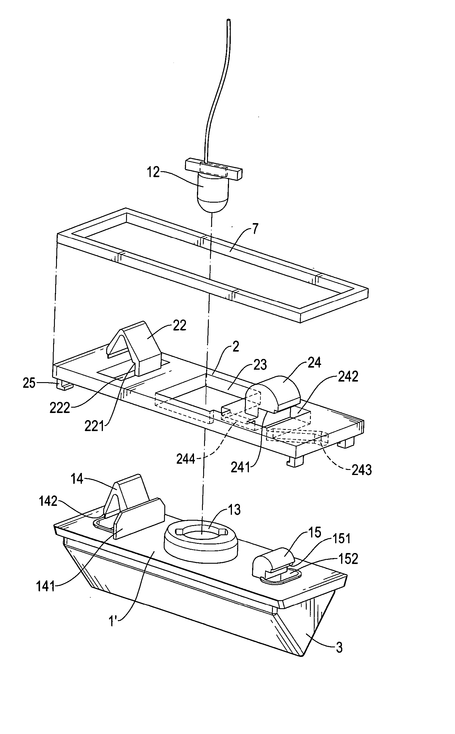
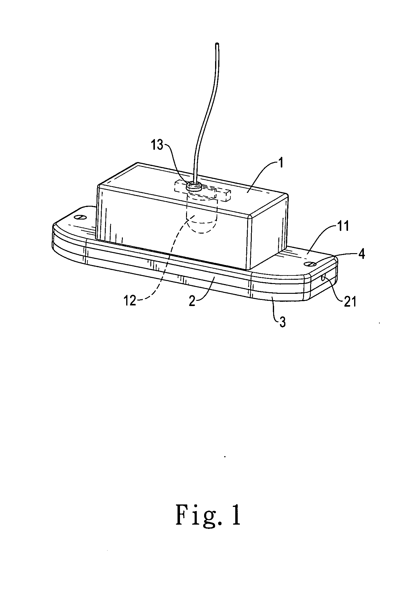
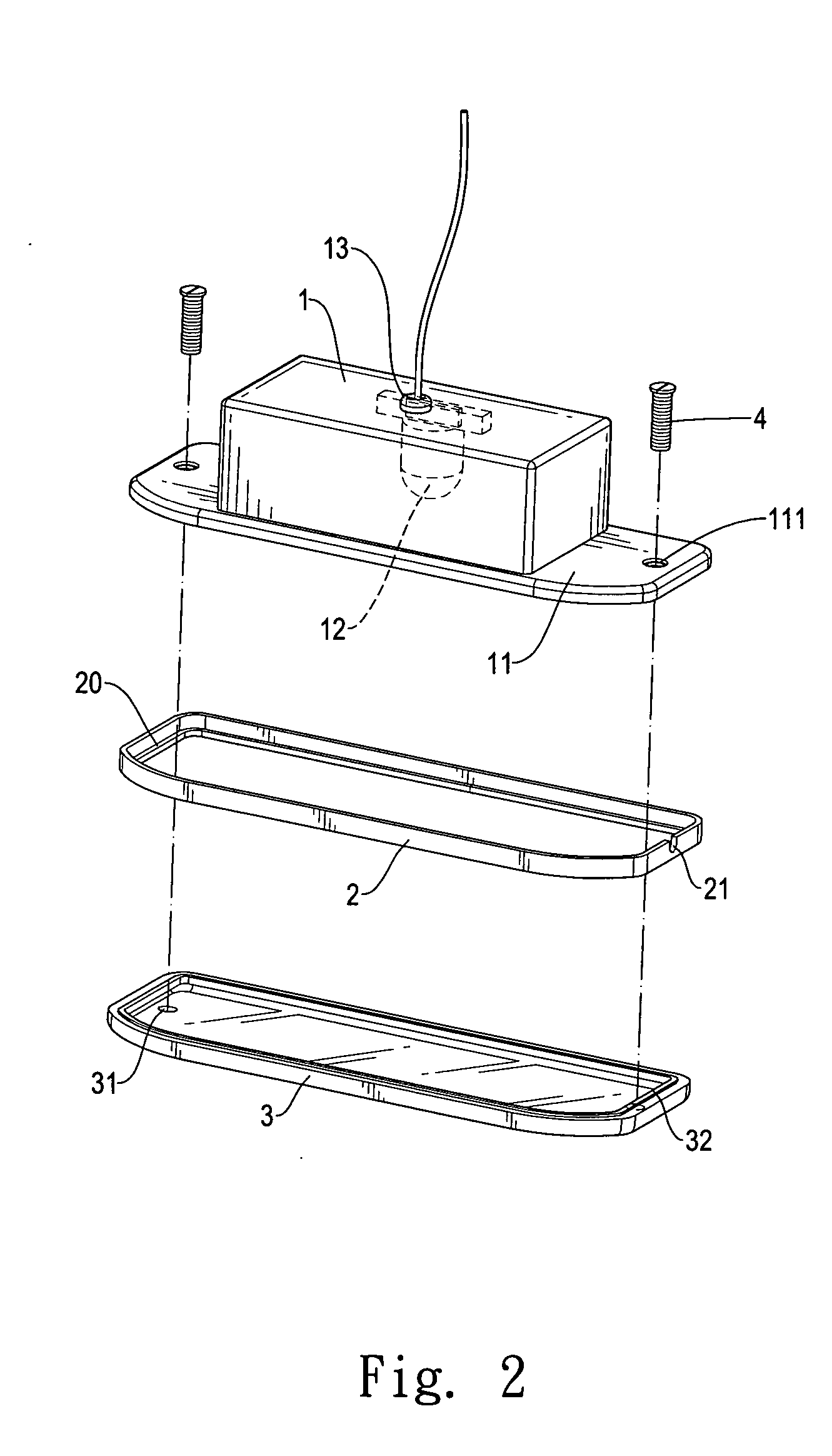
[0016] Referring to FIG. 1 through FIG. 4 simultaneously, a first preferred embodiment of a lamp structure of the present invention is shown. The lamp assembly comprises a top fixture, which is a top box 1 in this preferred embodiment, a frame body 2, and a transparent cover 3. A wire hole 13 is formed on the center of the top box 1. A light-emitting device 12 is coupled to the inside of top box 1, wherein the light-emitting device 12 is such as a light bulb or a light-emitting diode. A wire of the light-emitting device 12 is extended to the outside of the top box 1 via the wire hole 13. A protrudent flange 11 is extended horizontally from an opening of the top box 1. A coupling hole 111 is formed on both sides of the protrudent flange 11, respectively.

[0017] The frame body 2 has a shape conformal to the protrudent flange 11. A notch 21 is formed on one side of the frame body 2. A horizontal extension flange 20 is located inwardly on the other side of the frame body 2. In addition,...


PUM


Abstract

A lamp structure comprises a top fixture having a light-emitting device attached thereon; a frame body having a notch formed thereon; and a transparent cover, wherein the top fixture, the frame body, and the transparent cover are assembled together. As a result, a control wire of a video camera can be mounted easily by utilizing a wiring route of the light-emitting device via the notch of the frame body without damaging the original structure of the conventional lamp structure.

Description

FIELD OF THE INVENTION [0001] The present invention relates to an improved lamp structure that makes the mounting of a video camera easier and is suitable for various vehicles or the likes. BACKGROUND OF THE INVENTION [0002] By using the rearview mirrors mounted on both sides and the center of the vehicle, the driver can observe the surrounding images from the vehicle's seat. However, these rearview mirrors cannot reflect the images right behind the vehicle. In response to this, the vehicle is provided with the backing radar and the video camera. Besides, most vehicles are also provided with light sources above the license plates so as to show the license plate number clearly. [0003] However, the conventional license plate light and video camera are mounted independently. Two wiring routes must be provided in order to assemble both of them. As a result, it takes a long time for attaching the light sources and the video camera to the vehicle. It means that this vehicle is not availab...

Claims


Application Information

Patent Timeline
IPC IPC(8): B60R1/12F21S8/10
CPCB60Q1/56B60R11/04B60R2011/0003B60R2011/0042
Inventor CHANG
Owner COLITEC
Why Eureka
Try Eureka