System and method of multi-nodal APS control protocol signalling

a control protocol and protocol technology, applied in the field of automatic protection switching, can solve problems such as associated service interruption

Inactive Publication Date: 2007-11-01
WSOU INVESTMENTS LLC
View PDF8 Cites 27 Cited by
  • Summary
  • Abstract
  • Description
  • Claims
  • Application Information

AI Technical Summary

Problems solved by technology

Since the switching from the working circuit to the protection circuit is not local, communicating signals over the control link 140 to coordinat

Method used


Image

  • System and method of multi-nodal APS control protocol signalling
  • System and method of multi-nodal APS control protocol signalling
  • System and method of multi-nodal APS control protocol signalling

Examples


Embodiment Construction

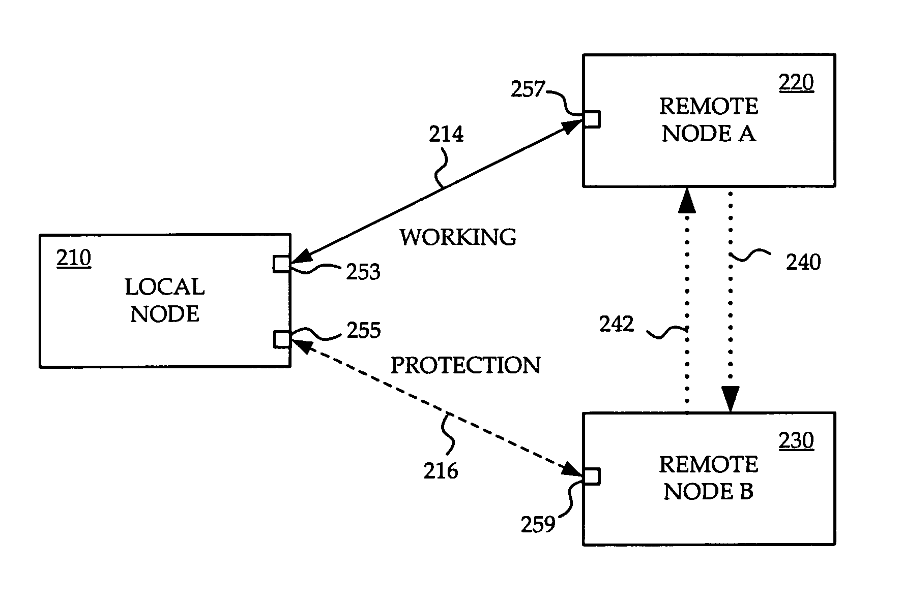
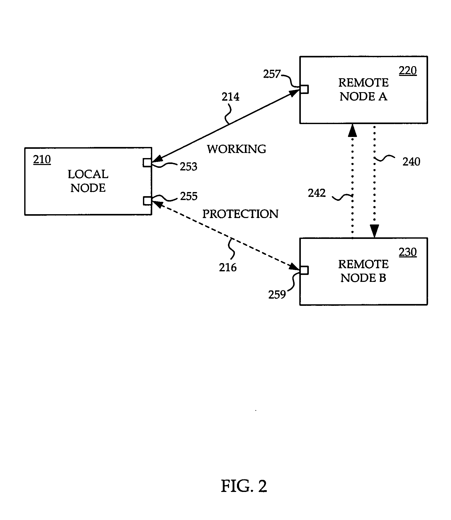
[0041] The preferred embodiment provides a multi-nodal (MN) APS 1+1 system architecture and control protocol. The protocol is light-weight and has low-overhead which reduces user traffic interruption due to a chassis failure, and minimizes system CPU usage. Efficiency is particularly important because the MN-APS control protocol is a high priority CPU task. Greater efficiency of this task allows for shorter intervals of communications between MN-APS peers, which decreases switchover times in response to failures, thereby reducing the duration and magnitude of traffic disruptions.

[0042] In an MN-APS 1+1 architecture, the remote working node and the remote protection node of an MN-APS group need to synchronize their MN-APS states and liveliness via a signaling protocol. Such a signaling protocol ideally is efficient and light-weight so that with little system CPU usage, an MN-APS node can switchover traffic with minimum traffic loss even with a large number of MN-APS groups.

[0043] R...


PUM


Abstract

A system and method for providing APS (automatic protection switching) redundant pair control protocol signaling for multi-nodal APS (MN-APS) is provided. Periodic liveliness messages are exchanged between each node of a redundant pair. Each liveliness message contains an IHY (I heard you) message which indicates whether or not the sender of the liveliness message received within a duration of a hold time a previously transmitted liveliness message from the recipient. When more than one MN-APS group is configured between two redundant nodes, liveliness messages are bundled together to reduce processing loads.

Description

FIELD OF THE INVENTION [0001] The invention relates to automatic protection switching (APS) in a communications network and more particularly to a system and method of for providing APS redundant pair control protocol signaling for multi-nodal APS (MN-APS). BACKGROUND OF THE INVENTION [0002] In providing communications services to customers, service providers attempt to ensure that services are delivered without loss of data and with minimal interruption. A well known approach to ensuring data transfer services is automatic protection switching or APS. In SONET / SDH, APS 1+1 is typically used for single chassis protection switching. [0003] Referring now to FIG. 1A, known single chassis APS 1+1 is discussed. A near end (NE) chassis 10 having SONET line-terminating equipment (LTE) whose data traffic is to be protected, has an NE working port 21 which is coupled via a bidirectional working link 14 to a far end (FE) working port 23 of an FE chassis 20 having SONET LTE. The NE chassis 10 ...

Claims


Application Information

Patent Timeline
IPC IPC(8): H04J3/14
CPCH04J3/14H04J2203/006H04L45/28H04L45/22H04L45/00
Inventor SAHA, KAJALHART, NEIL DARRENGRIGORIU, TIBERIU
Owner WSOU INVESTMENTS LLC
Why Eureka
Try Eureka