
Electrical connector

a technology of electrical connectors and connectors, applied in the direction of electrical apparatus, coupling device connections, printed circuits, etc., can solve the problems of electrical terminals with higher stress concentration elastic fatigue of electrical terminals, etc., and achieve less elastic fatigue, lower normal force, and less stress concentration

Inactive Publication Date: 2007-11-01
LOTES
View PDF6 Cites 0 Cited by
  • Summary
  • Abstract
  • Description
  • Claims
  • Application Information

AI Technical Summary

Benefits of technology

[0004] An object of the present invention is to provide an electrical connector in which the deforming contact between the electrical terminal and the insulating body can be enhanced.
[0006] Compared with the conventional prior art, the electrical connector according to the present invention has the advantages described below. The structure of the electrical connector according to the present invention can have lower stress concentration, less elastic fatigue, and higher normal force for the electrical terminal.

Problems solved by technology

However, the kind of electrical terminal structure tends to suffer from elastic fatigue and the electrical terminal is encountered with higher stress concentration as well as lower normal force.

Method used


Image

  • Electrical connector
  • Electrical connector
  • Electrical connector

Examples


Embodiment Construction

[0020] Referring to FIGS. 1 to 6, the electrical connector according to the present invention comprises a plurality of insulating bodies 10 and electrical terminals 20 provided in the insulating body 10, respectively.

[0021] The insulating body 10 comprises a receiving chamber 100 and two locating grooves 101, wherein at least one contact face 1000 is provided on one of its sides the receiving chamber 100. The contact face 1000 is, for example but not limited to, arc shape. The electrical terminal 20 is deformingly contacted with the arc contact face 1000 of the receiving chamber 1000 to evenly distribute the stress resulted from the deformation of the electrical terminal 20. Furthermore, the two locating grooves 101 are separated by a separating block 102, and the locating grooves 101 and the receiving chamber 100 is connected.

[0022] In particular, the radial normal force increases when the curvature of the arc contact face 1000 of the receiving chamber 100 is increased. The expla...


PUM


Abstract

An electrical connector includes an insulating body provided with a plurality of receiving chambers, each of which is provided with an arc contact face on at least one of its sides; and at least one electrical terminal received in the receiving chamber to deformingly contact with the arc contact face. Compared with the conventional prior art, the structure of the electrical connector according to the present invention can have lower stress concentration, less elastic fatigue, and higher normal force for the electrical terminal.

Description

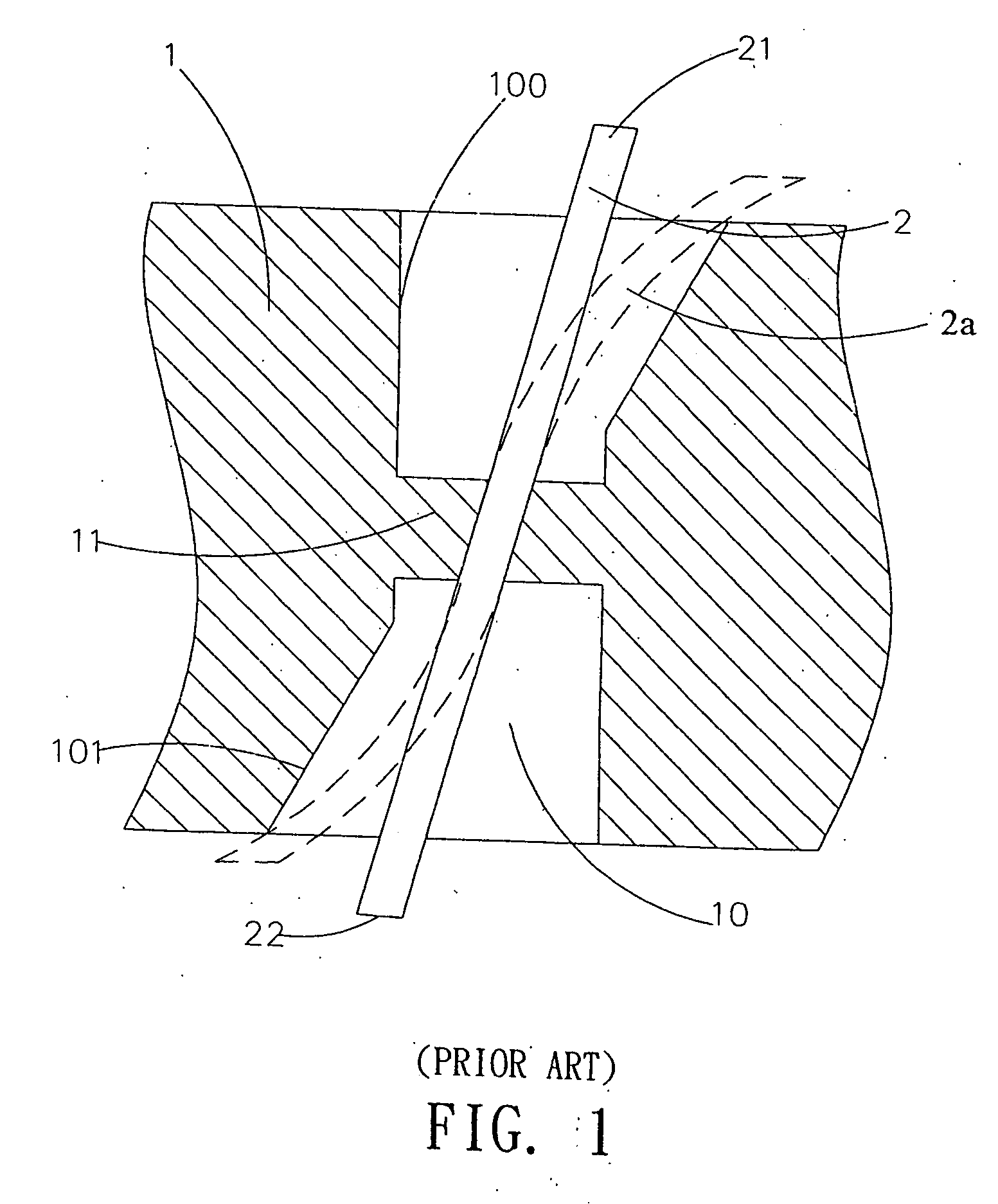
FIELD OF THE INVENTION [0001] The present invention relates to an electrical connector, and more particularly, to an electrical connector which can enhance deforming contact between the electrical terminal and the insulating body. BACKGROUND OF THE INVENTION [0002] The conventional prior art of electrical connector, PRC Patent No., CN200420088694.0 for example, discloses an electrical connector, as shown in FIG. 1, comprising an insulating body 1 provided with a plurality of receiving chambers 10, and an electrical terminal 2 received in the insulating body 1, wherein the wall of the receiving chamber 10 comprising a vertical portion 100 and an inclined portion 101. The electrical terminal 2 has a certain extent of elasticity and is of a straight shape. The electrical terminal 2 arranged in the insulating body 1 of the electrical connector is retained by a stop block 11, wherein both ends of the electrical terminal 2 protrude over the upper and lower surfaces of the insulating body ...

Claims


Application Information

Patent Timeline
Patent Type & Authority Applications(United States)
IPC IPC(8): H01R12/00
CPCH01R13/2435
Inventor JU, TED
Owner LOTES
Learn More