Light bulb theft-reduction apparatus and method of use
a technology for applied in the field of theft reduction devices and techniques, can solve the problems of public facilities facing a constant problem of petty theft, owners facing the cost of theft deterrents versus the cost of theft itself, and it makes little sense to place rfid, so as to prevent accidental removal, less subject to theft, and the effect of reducing the cost of th
- Summary
- Abstract
- Description
- Claims
- Application Information
AI Technical Summary
Benefits of technology
Problems solved by technology
Method used
Image
Examples
first embodiment
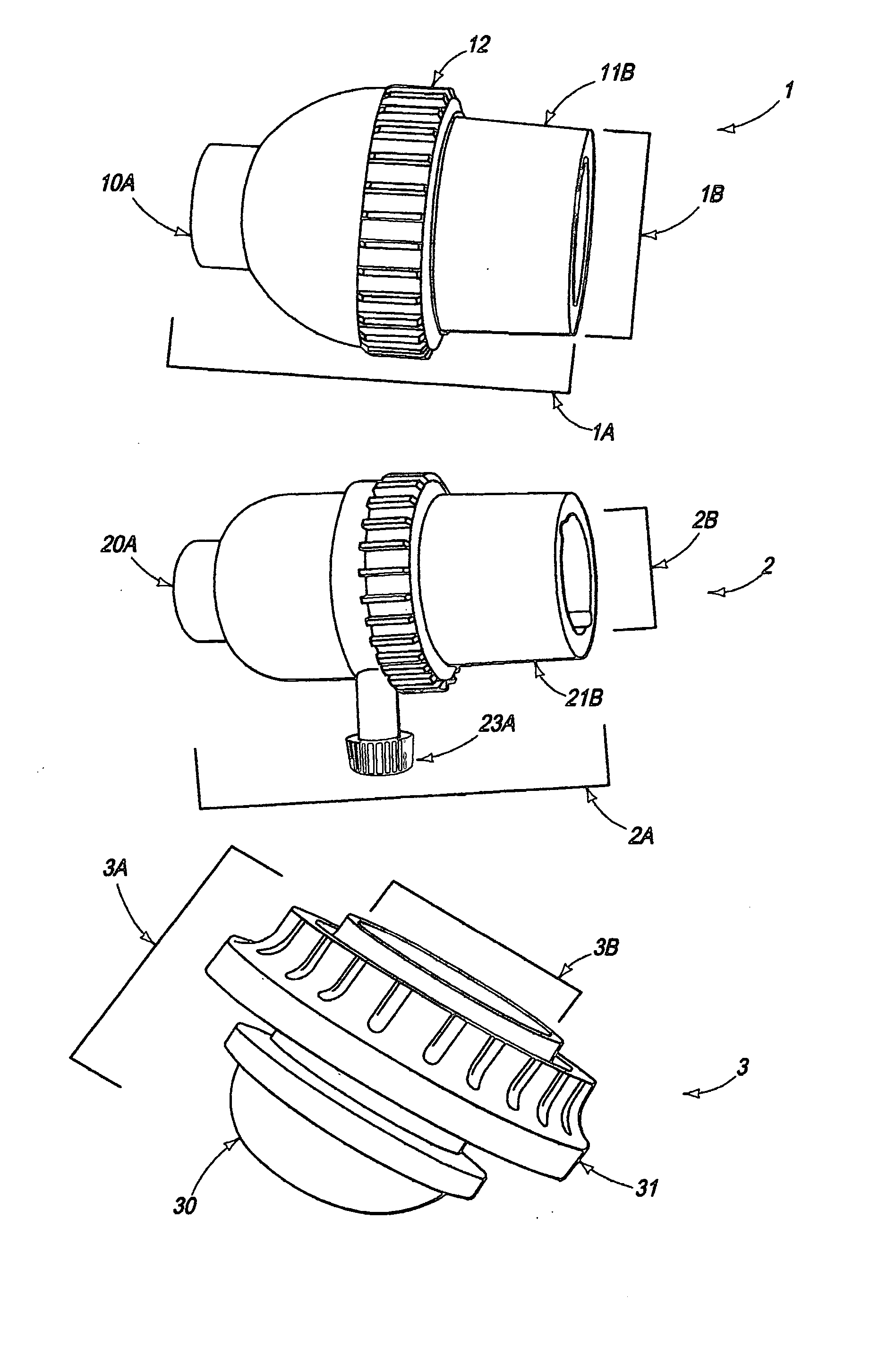
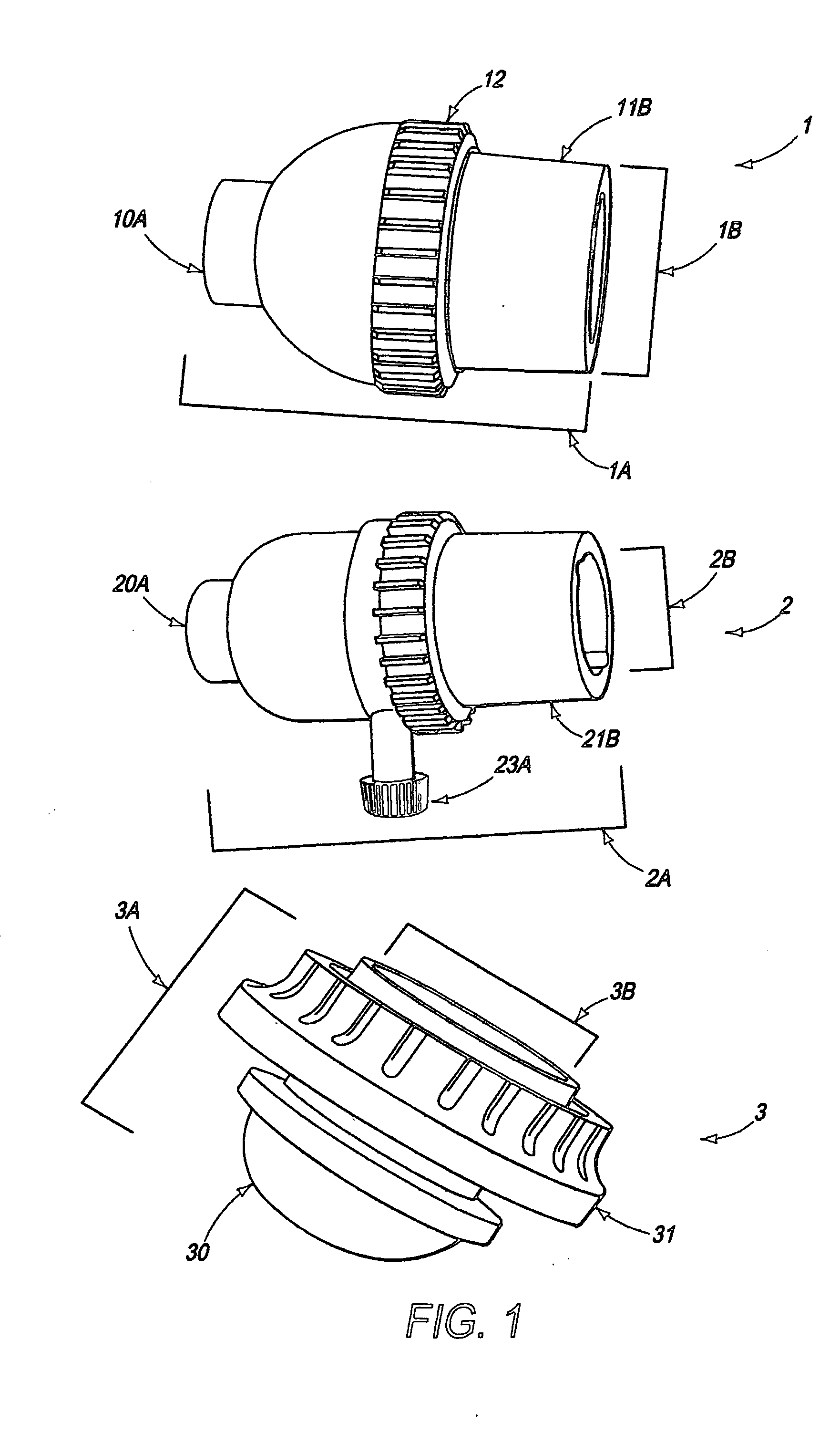
[0035] To assemble the first aspect, top section 11 is placed against bottom section 10 in such a way that nubs 11D engage notches 10C. Ring connector 12 is then threaded onto threaded body nipple 10B of bottom section 10 until retaining lip 12C engages fitting lip 11C of the top section.
[0036] As shown in FIG. 1, a second embodiment of the first aspect of the invention comprises a switched GU10-modified light fixture 2. The fixture comprises a housing 2A and a socket 2B for holding the base of a light bulb. The housing is made of a phenolic substance, or any other material which is light weight, durable and generally non-conductive of household levels of electricity. It is designed to be installed on common electric lamps, of the variety typically found in retail stores. As shown in FIG. 5, the housing of the first embodiment comprises a bottom section 20, a top section 21, a ring connector 22 and a switch compartment 23.
[0037] Bottom section 20 comprises a threaded lamp coupling ...
second embodiment
[0039] To assemble the first aspect, top section 21 (with attached switch compartment 23) is placed against bottom section 20 in such a way that thumbscrew 23A engage positioning slot 20C. Ring connector 22 is then threaded onto threaded body nipple 20B of bottom section 20 until retaining lip 22C engages fitting lip 21C of the top section.
[0040] As shown in FIG. 1, a third embodiment of the first aspect comprises a screw-ring GU10-modified light fixture 3. The fixture comprises a housing 3A and a socket 3B for holding the base of a light bulb. The housing is made of a phenolic substance, or any other material which is light weight, durable and generally non-conductive of household levels of electricity. It is designed to be installed on common electric lamps, of the variety typically found in retail stores. As shown in FIG. 6, the housing of the first embodiment comprises a bottom section 30 and a shade connecting ring 31.
[0041] Bottom section 10 comprises a threaded lamp attachme...
third embodiment
[0045] To assemble the first aspect, as alluded to above, connections insert 32 is slid into bottom section 30 until notches 32C engage ridges 30C. Next spacing ring 33 is threaded into internal threads 30D of the bottom section, securing insert 32 in place. Finally, if the structural ring of a lampshade or lampshade support (not shown, but a common step in the art) has been placed Into position on the bottom section, shade connecting ring 31 is threaded onto the threaded body nipple 30B to secure the lampshade in place.
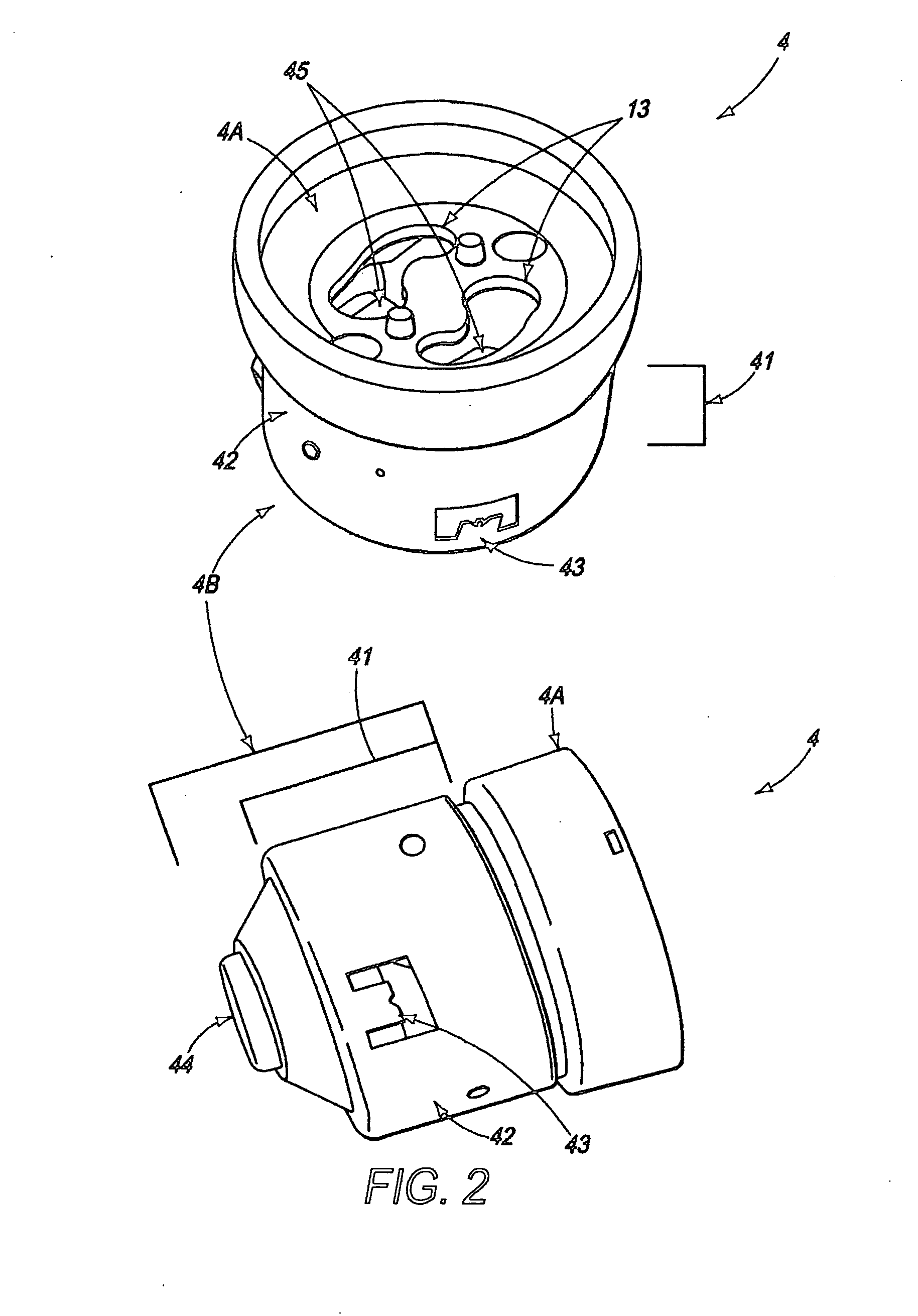
[0046]FIG. 2 illustrates the second aspect of the apparatus, the GU10 socket-converting adapter 4. The adapter comprises a male insert section 4A and a socket 4B. The insert section comprises a cylindrical body 41, made of phenolic or any other material which is light weight, durable and generally non-conductive of household levels of electricity. The insert is sized to be able to easily slide into the socket of a common retail lamp's light bulb holding fixture. The ...
PUM
 Abstract
Description
Claims
Application Information
 - R&D
- Intellectual Property
- Life Sciences
- Materials
- Tech Scout
- Unparalleled Data Quality
- Higher Quality Content
- 60% Fewer Hallucinations
Browse by: Latest US Patents, China's latest patents, Technical Efficacy Thesaurus, Application Domain, Technology Topic, Popular Technical Reports.
© 2025 PatSnap. All rights reserved.Legal|Privacy policy|Modern Slavery Act Transparency Statement|Sitemap|About US| Contact US: help@patsnap.com


