Receiving operation control device, receiving operation control method, and computer-readable storage medium

a technology of operation control device and operation control method, which is applied in the direction of substation equipment, electrical equipment, broadcast service distribution, etc., can solve the problems of user not being aware of the call termination sound or the vibration of the vibrator

Inactive Publication Date: 2007-11-01
FUJITSU LTD
View PDF8 Cites 25 Cited by
  • Summary
  • Abstract
  • Description
  • Claims
  • Application Information

AI Technical Summary

Benefits of technology

[0019]On the other hand, the present invention provides a computer-readable storage medium for storing a program that, assuming that moving states of a mobile communication equipment associated with combination patterns of positioning detection patterns relevant to the positions of the mobile communication equipment that may be detected by a positioning sensor incorporated in the mobile communication equipment and vibration detection patterns relevant to levels of vibration that may be detected by a vibration sensor incorporated in the mobile communication equipment are registered in advance, and receiving operation patterns associated with the moving states are registered in advance, allows a computer to decide the moving state of the mobile communication equipment on the basis of the positioning detection pattern and vibration detection pattern detected by the positioning sensor and vibration sensor, respectively, when a call is terminated at the mobile communication equipment; to select a receiving operation pattern associated with the moving state according to the result of the decision of the moving state; and to designate at least one of the volume of a call termination sound to be generated by the mobile communication equipment and the magnitude of vibration, which are associated with the receiving operation pattern, according to the result of the selection of the receiving operation pattern.

Problems solved by technology

Consequently, assuming that the user of the mobile communication equipment is moving (for example, the user is walking or running), even if a call termination sound is generated or a vibrator is operated in order to inform the user of the fact that a call has been terminated, the user may be unaware of the call termination sound or the vibration of the vibrator, due to ambient vibration or noise near the mobile communication equipment.
However, none of Patent Documents No. 1 to No. 3 refer to a concrete technique for automatically deciding the moving state of a mobile communication equipment using a positioning sensor (for example, a global positioning system (GPS) sensor) incorporated in the mobile communication equipment and a vibration sensor in combination, and automatically designating the volume of a call termination sound or the magnitude of vibration of a vibrator according to the decided moving state.
Consequently, the same problem, as in the aforesaid conventional mobile communication equipment, may occur in each equipment described in Patent Documents No. 1 to No. 3.

Method used


Image

  • Receiving operation control device, receiving operation control method, and computer-readable storage medium
  • Receiving operation control device, receiving operation control method, and computer-readable storage medium
  • Receiving operation control device, receiving operation control method, and computer-readable storage medium

Examples


Embodiment Construction

[0033]Referring to the appended drawings (FIG. 1 to FIG. 8), constituent features of some preferred embodiments of the present invention, and operations to be performed in the embodiment, will be described below.

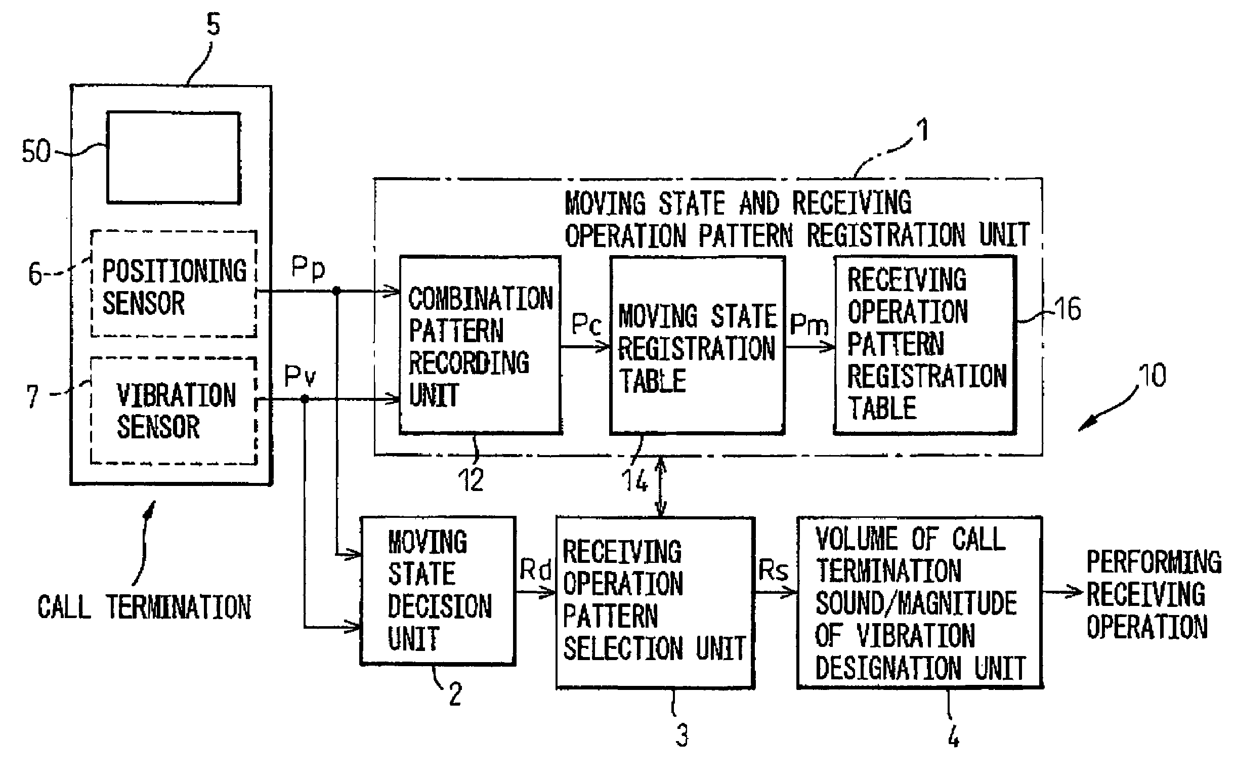
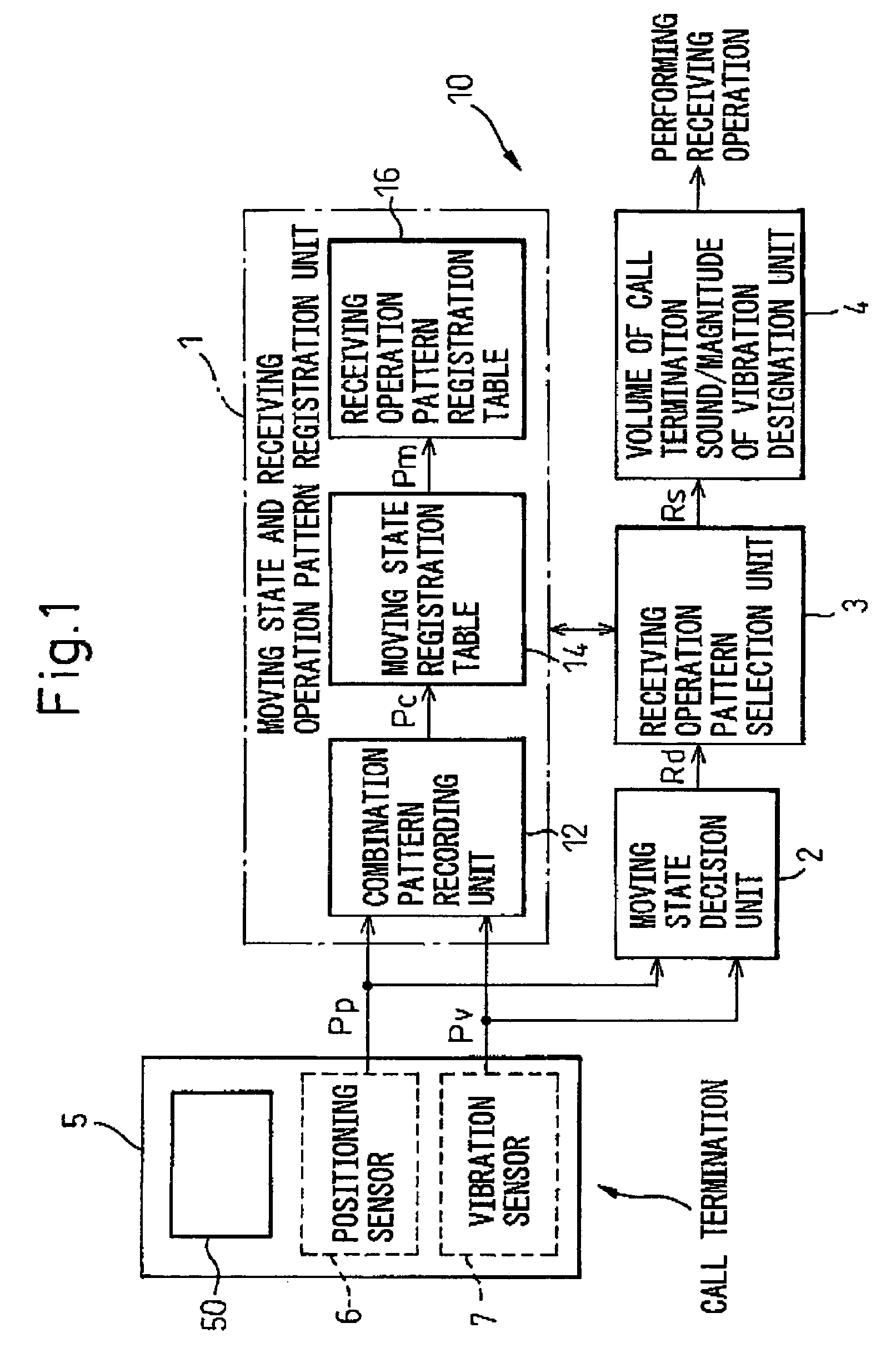
[0034]FIG. 1 is a block diagram showing the configuration of a receiving operation control device in accordance with an embodiment of the present invention. Herein, the configuration of a receiving operation control device 10 in accordance with the embodiment of the present invention is shown schematically. Hereinafter, the same reference numerals will be assigned to any components substantially identical to the aforesaid components.

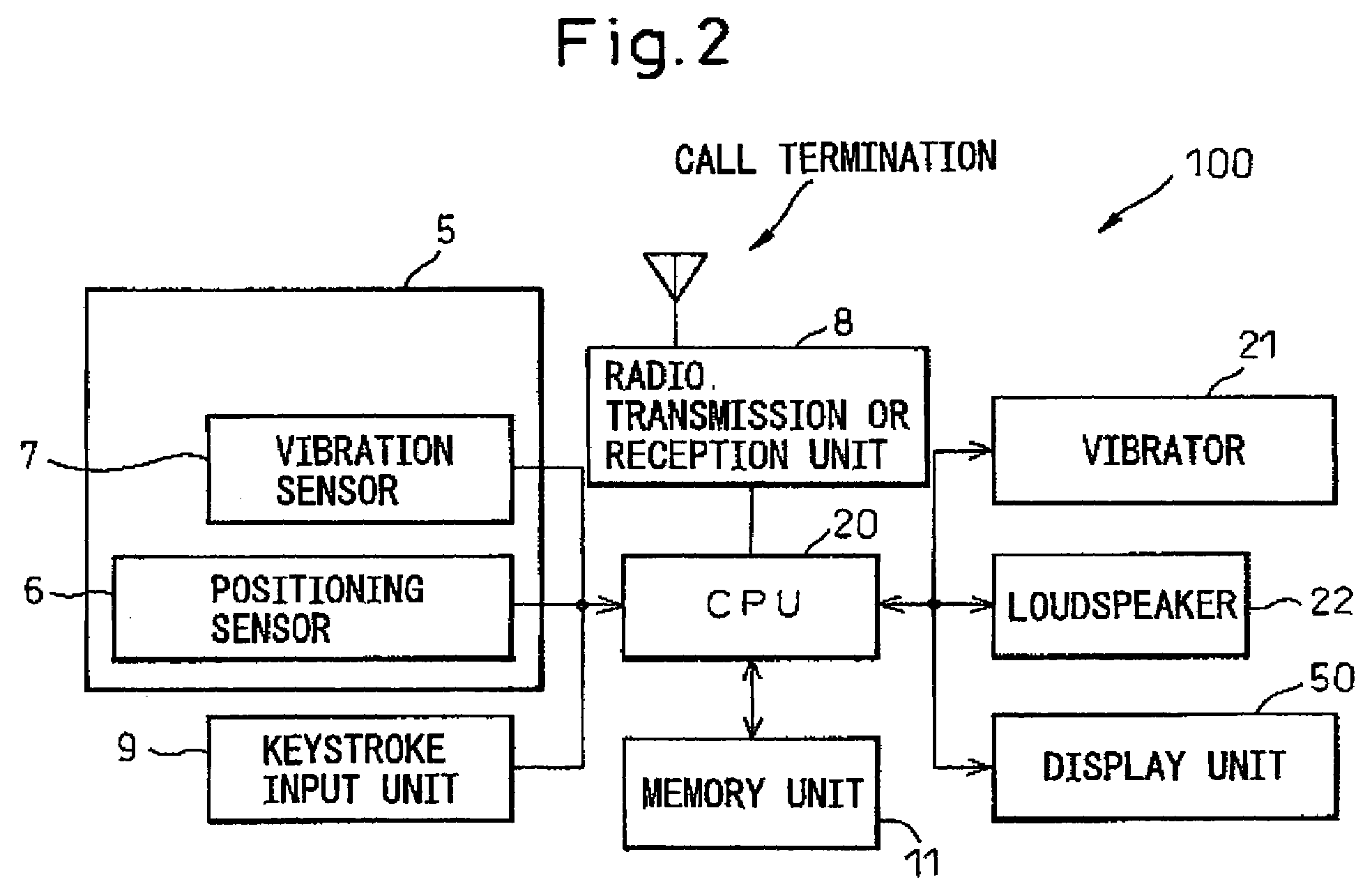
[0035]As shown in FIG. 1, a mobile communication equipment 5, such as a portable cellular phone or a handheld device, includes a display unit 50 on which data, entered through a keystroke input unit (for example, see FIG. 2 that will be mentioned below), is displayed or on which a progress of data transmission or reception is displayed.

[0036]Furt...


PUM


Abstract

A call-termination operation control device that controls the volume of a call termination sound or the magnitude of vibration of a vibrator for the purpose of informing a user of a mobile communication equipment of the fact that a call has been terminated includes a moving state and receiving operation pattern registration unit in which combinations of positioning detection patterns and vibration detection patterns detected by a positioning sensor and a vibration sensor are recorded, moving states associated with the combinations are registered, and receiving operation patterns associated with the moving states are registered; a moving state decision unit that decides the moving state on the basis of the positioning detection pattern and vibration detection pattern which are detected at the time of call termination; a receiving operation pattern selection unit that selects a receiving operation pattern associated with the moving state according to the result of the decision; and a volume of call termination sound/magnitude of vibration designation unit that designates the volume of a call termination sound and the magnitude of vibration, which are associated with the receiving operation pattern, according to the result of the selection. Also disclosed are a receiving operation control method for controlling the volume of a call termination sound or the magnitude of vibration as mentioned above.

Description

BACKGROUND OF THE INVENTION[0001]1. Field of the Invention[0002]The present invention relates to a receiving operation control device (or a call termination operation control device) and the receiving operation control method that appropriately control the volume of a call termination sound and the magnitude of vibration of a vibrator or the like, so as to perform a receiving operation for the purpose of informing a user of a mobile communication equipment, such as a portable cellular phone or a handheld device, of the fact that a call has been terminated (i.e., the fact that a call has been received). The present invention also relates to computer-readable storage medium for storing a program for implementing the above method.[0003]2. Description of the Related Art[0004]In general, a mobile communication equipment, such as a portable cellular phone or a handheld device, that adopts a wideband code division multiple access (W-CDMA) technique, has been designed so that a user of the ...

Claims


Application Information

Patent Timeline
Patent Type & Authority Applications(United States)
IPC IPC(8): H04M11/04H04W64/00H04W4/10H04W88/16
CPCH04M1/72572H04M2250/12H04M2250/10H04M19/04H04M1/72457
Inventor KIKUCHI, YOSHIAKIIDA, TOHRUNAKAJIMA, YUKOETO, MASAMINAKANO, MAKOTOEBARA, TAKAYUKIAKAMA, KATSUAKI
Owner FUJITSU LTD
Why Eureka
Try Eureka