
Value-based memory coherence support

Active Publication Date: 2007-11-01
ORACLE INT CORP
View PDF3 Cites 11 Cited by
  • Summary
  • Abstract
  • Description
  • Claims
  • Application Information

AI Technical Summary

Benefits of technology

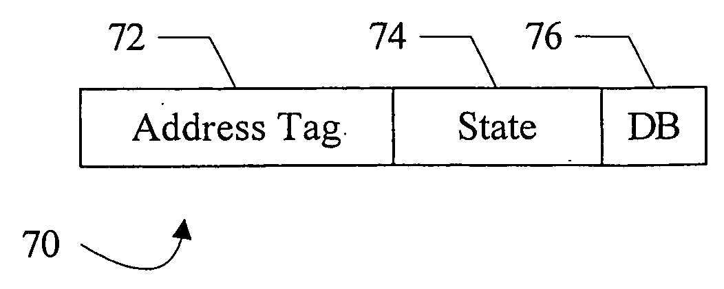
[0007] In another embodiment, a cache comprises a data memory configured to store a plurality of cache lines of data, a tag memory configured to store a plurality of cache tags corresponding to the plurality of cache lines, and a control unit coupled to the data memory and the tag memory. Each of the plurality of cache tags comprises an indication of whether or not the corresponding cache line is storing one or more data values that match a designated value, wherein the designated value indicates t

Problems solved by technology

While hardware coherence mechanisms simplify the software that executes on the system, the hardware coherency mechanisms may be complex and expensive to implement (especially in terms of design time).
Additionally, if errors in the hardware coherence implementation are found, repairing the errors may be costly (if repaired via hardware modification) or limited (if software workarounds are used).
While software mechanisms are more easily repaired if an error is found and are more flexible if changing the coherence scheme is desired, they typically have much lower performance than hardware mechanisms.

Method used


Image

  • Value-based memory coherence support
  • Value-based memory coherence support
  • Value-based memory coherence support

Examples


Embodiment Construction

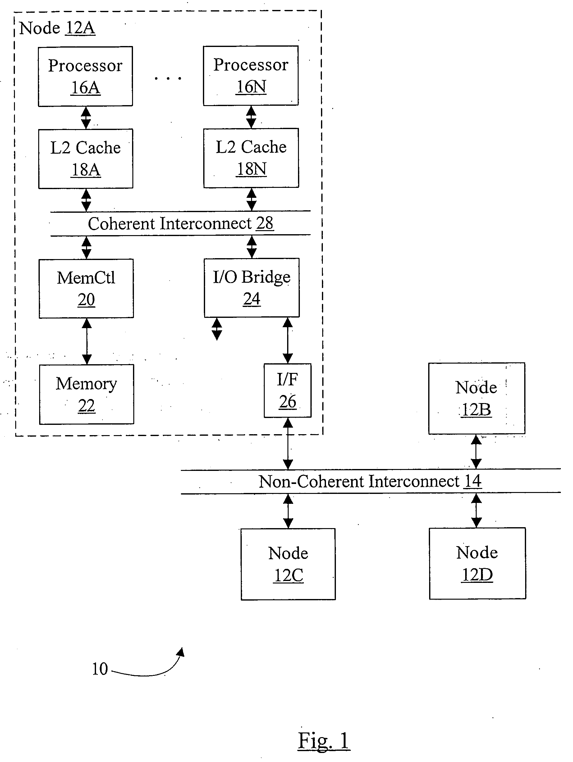
[0019] Turning now to FIG. 1, a block diagram of one embodiment of a system 10 is shown. In the illustrated embodiment, the system 10 comprises a plurality of nodes 12A-12D coupled to a non-coherent interconnect 14. The node 12A is shown in greater detail for one embodiment, and other nodes 12B-12D may be similar. In the illustrated embodiment, the node 12A includes one or more processors 16A-16N, corresponding L2 caches 18A-18N, a memory controller 20 coupled to a memory 22, an input / output (I / O) bridge 24 coupled to one or more I / O interfaces including an interface 26 to the interconnect 14. In the illustrated embodiment, the L2 caches 18A-18N are coupled to respective processors 16A-16N and to a coherent interconnect 28. In other embodiments, a given L2 cache may be shared by two or more processors 16A-16N, or a single L2 cache may be shared by all processors 16A-16N. In still other embodiments, the L2 caches 18A-18N may be eliminated and the processors 16A-16N may couple directl...


PUM


Abstract

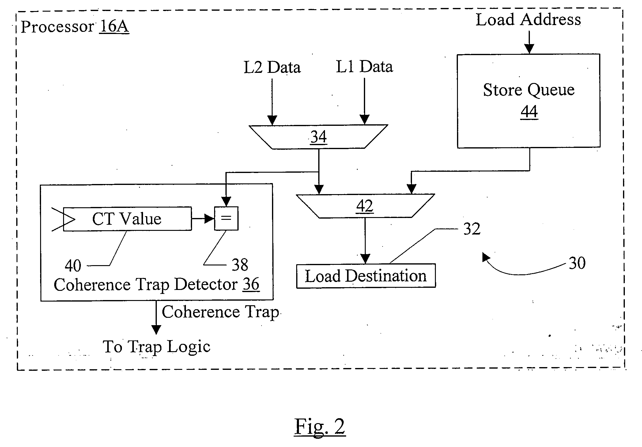
In one embodiment, a processor comprises a coherence trap unit and a trap logic coupled to the coherence trap unit. The coherence trap unit is also coupled to receive data accessed in response to the processor executing a memory operation. The coherence trap unit is configured to detect that the data matches a designated value indicating that a coherence trap is to be initiated to coherently perform the memory operation. The trap logic is configured to trap to a designated software routine responsive to the coherence trap unit detecting the designated value. In some embodiments, a cache tag in a cache may track whether or not the corresponding cache line has the designated value, and the cache tag may be used to trigger a trap in response to an access to the corresponding cache line.

Description

BACKGROUND [0001] 1. Field of the Invention [0002] This invention is related to the field of computer systems and, more particularly, to coherence mechanisms in computer systems. [0003] 2. Description of the Related Art [0004] Historically, shared memory multiprocessing systems have implemented hardware coherence mechanisms. The hardware coherence mechanisms ensure that updates (stores) to memory locations by one processor (or one process, which may be executed on different processors at different points in time) are consistently observed by all other processors that read (load) the updated memory locations according to a specified ordering model. Implementing coherence may aid the correct and predictable operation of software in a multiprocessing system. While hardware coherence mechanisms simplify the software that executes on the system, the hardware coherency mechanisms may be complex and expensive to implement (especially in terms of design time). Additionally, if errors in the...

Claims


Application Information

Patent Timeline
IPC IPC(8): G06F13/28
CPCG06F12/0808G06F12/0897G06F12/0822G06F12/0815
Inventor ZEFFER, HAKANHAGERSTEN, ERIKLANDIN, ANDERSCHAUDHRY, SHAILENDERLOEWENSTEIN, PAULCYPHER, ROBERTRADOVIC, ZORAN
Owner ORACLE INT CORP
Learn More