
Automotive Airbag Device

a technology for airbags and autos, applied in the field of airbags, can solve the problems of gas guide members vibrating with unstable oscillations, damage to airbag seams, and defeating the purpose of gas guide members

Inactive Publication Date: 2007-11-08
AUTOLIV DEV AB
View PDF18 Cites 11 Cited by
  • Summary
  • Abstract
  • Description
  • Claims
  • Application Information

AI Technical Summary

Benefits of technology

[0016] The airbag of the present invention has the effect of stabilizing the flow of gas into an airbag equipped with a gas guide member as a means of directing the flow of gas from an insertion end of a gas generator into the airbag.

Problems solved by technology

It has been determined, however, that forming the gas guide member from a soft material results in the gas guide member vibrating with unstable oscillations due to the pressure of the flowing gas.
This vibration has a destabilizing effect on the gas flow direction, and thus defeats the purpose of the gas guide member.
Moreover, the high temperature gas may damage the airbag seams, especially those seams placed in proximity to the insertion end of the gas generator.
These factors have the potential to adversely affect the performance and dependability of airbag operation.

Method used


Image

  • Automotive Airbag Device
  • Automotive Airbag Device
  • Automotive Airbag Device

Examples


Embodiment Construction

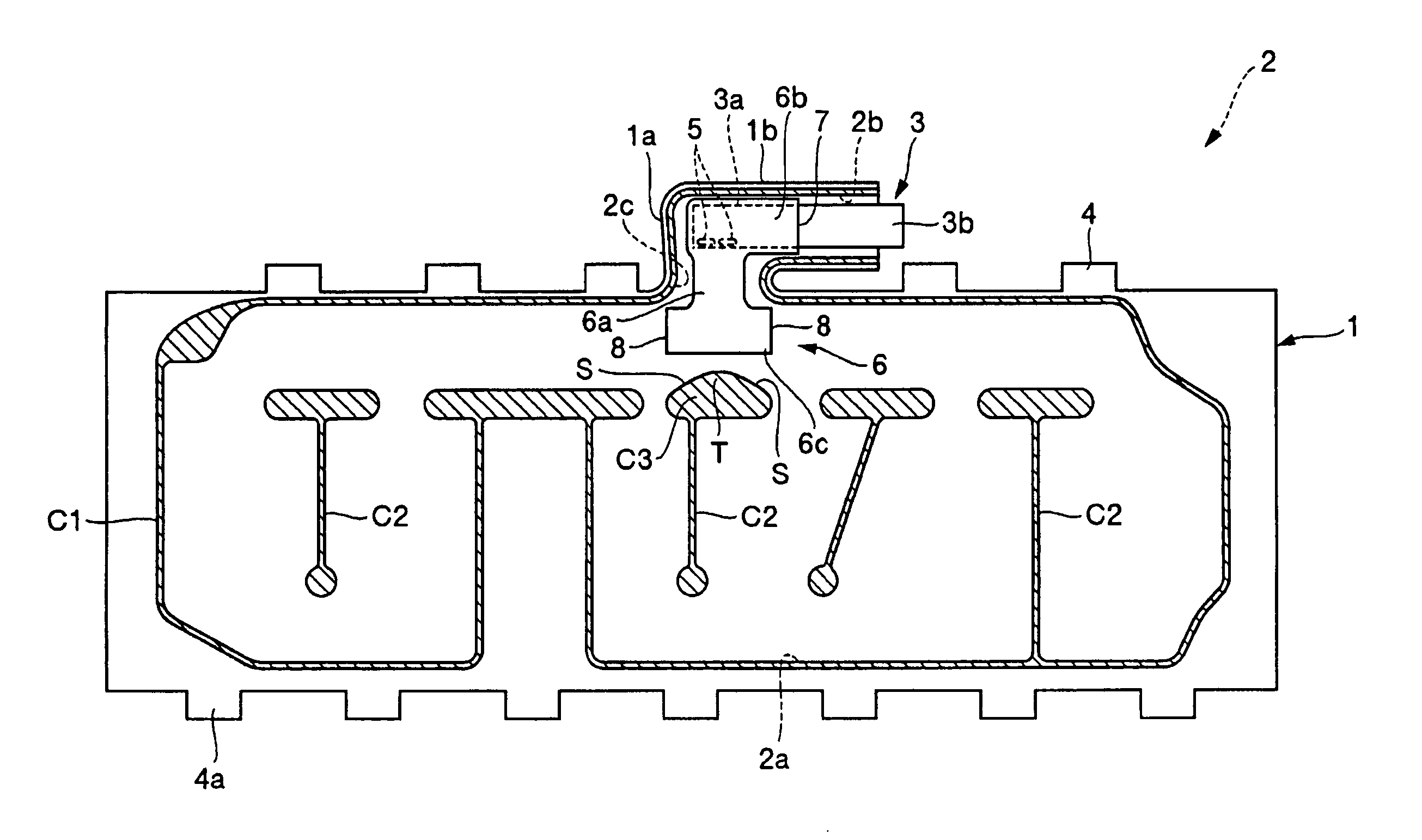
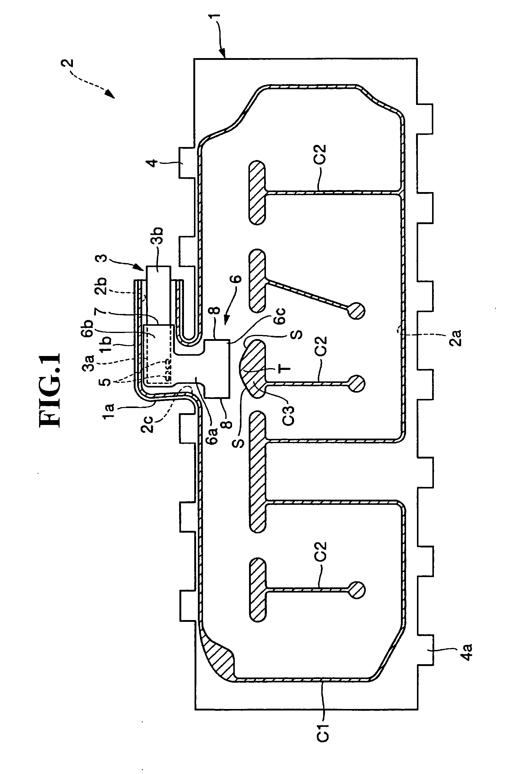
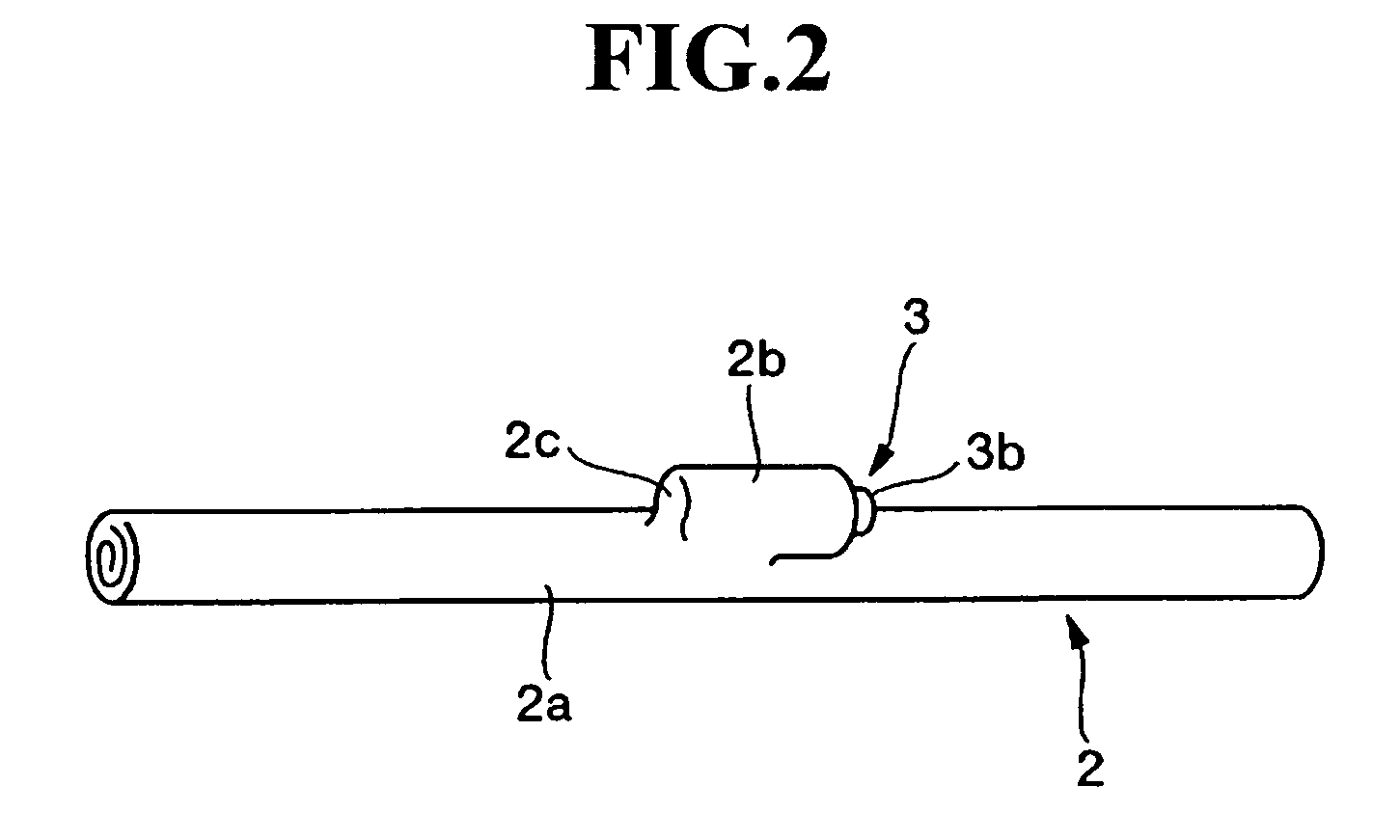
[0022] The following provides a detailed description of a preferred embodiment of the invention with reference to the attached drawings. The automotive airbag according to the present invention is embodied here in the form of a side impact or curtain airbag comprising, as shown in FIGS. 1 and 2, a pouch-shaped airbag 2 formed from fabric layers 1, and a gas generator 3 which inflates the airbag 2 by injecting gas therein.

[0023] The embodiment of the airbag 2 described in the drawings is constructed by joining the overlapping and mutually facing fabric layers 1. Each fabric layer 1 is formed to a length approximately equivalent to the combined length of the front and rear seats in the fore-aft direction, and to a height sufficient to cover the vertical dimension of the side windows. Fastening tabs 4 are located on the perimeter of the airbag 2 as means of attaching the airbag 2 to the vehicle body, and tie tabs 4a are also provided on the perimeter of the airbag 2 as means of mainta...


PUM


Abstract

An airbag is formed from fabric layers joined at a seam, and gas generator inflates the airbag by means of gas expelled from the gas generator's insertion end which has been inserted into the airbag. A gas guide is formed in the airbag in order to direct gas from the gas generator into the airbag and includes a pouch-shaped gas guide member in which are formed gas injection nozzles and an attachment orifice. The insertion end of the gas generator is inserted into the attachment orifice with the gas injection nozzles facing an interior of the airbag. A convex-shaped seam is included where the fabric layers are joined, and is disposed in opposition to the gas guide member. The gas guide member comes into contact with the convex-shaped seam as a result of the pressure of the flow of gas from the gas generator through the gas guide member.

Description

CROSS REFERENCE TO RELATED APPLICATIONS [0001] This application claims priority to PCT / JP2004 / 017688 filed Nov. 29, 2004 and to Japanese Patent Application No. 2003-409340 filed Dec. 8, 2003.BACKGROUND [0002] 1. Field of the Invention [0003] The present invention relates to an airbag for use in motor vehicles. In particular it relates to a side airbag which uses a guide member to stabilize the flow of gas emitted from a gas generator into the airbag. [0004] 2. Description of Related Art [0005] An airbag installed on the sides of the interior of a vehicle passenger compartment, and in particularly extended from the front seat region to the rear seat region, is commonly called a “side airbag” or “curtain airbag” in the art. When a side impact occurs, gas inflates the airbag which then expands, drops down from the passenger compartment ceiling, and covers the window, much like a curtain, in order to protect the passenger from injury. An airbag utilizing this type of structure is formed...

Claims


Application Information

Patent Timeline
IPC IPC(8): B60R21/16B60R21/233B60R21/26B60R21/261
CPCB60R21/233B60R21/26B60R2021/2617B60R2021/23316B60R2021/161
Inventor FUKUDA, MASATAKAYOSHIDA, YUICHIROHIGANO, MAKOTONOGAMI, MITSUOSHIMIZU, TARO
Owner AUTOLIV DEV AB
Learn More