Vehicle and vehicle substructure

Inactive Publication Date: 2011-04-28
TOYOTA JIDOSHA KK
View PDF27 Cites 7 Cited by
  • Summary
  • Abstract
  • Description
  • Claims
  • Application Information

AI Technical Summary

Benefits of technology

[0006]Therefore, the invention is to provide a vehicle and a vehicle sub

Problems solved by technology

Without any aerodynamic equipment provided under the floor of a car body, a flow of air under the floor of the car body cannot be stabilized and therefore cannot be diffused smoothly at a rear end of the vehicle.
Consequently, stability of the vehicle is deteriorated and air resistance increases.
However, in the diffuser and the rectifying fin provided on the flat plate, not much change in the flow of air is o

Method used


Image

  • Vehicle and vehicle substructure
  • Vehicle and vehicle substructure
  • Vehicle and vehicle substructure

Examples


Embodiment Construction

[0020]Embodiments of the vehicle substructure according to the invention are now described hereinafter with reference to the drawings.

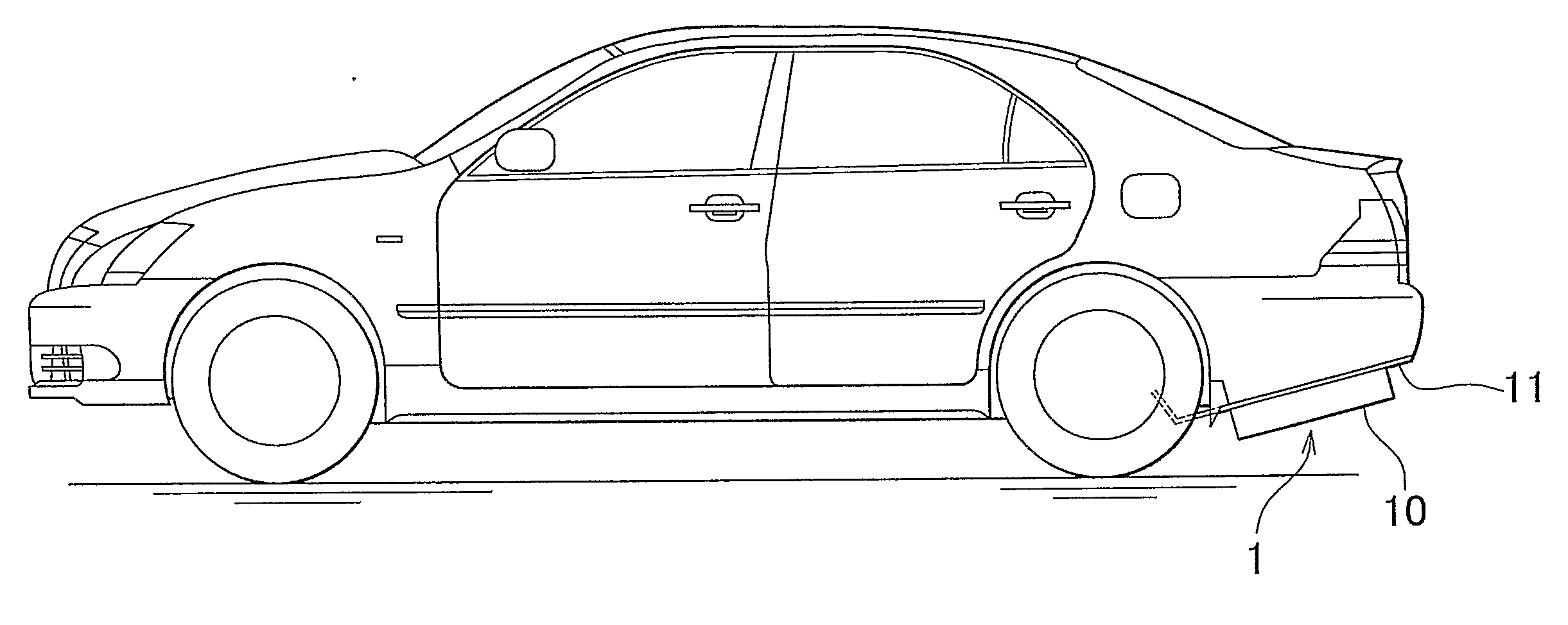
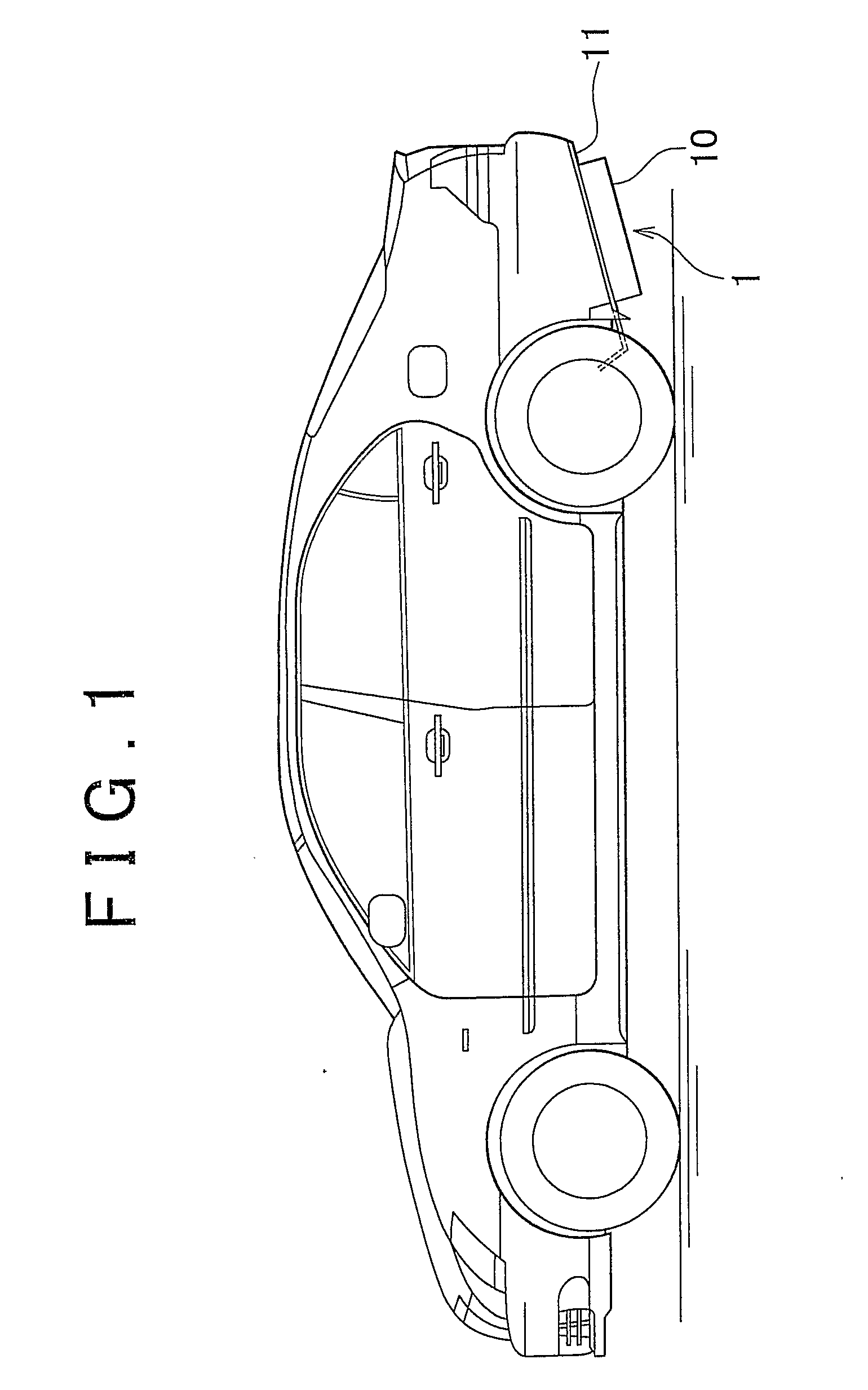
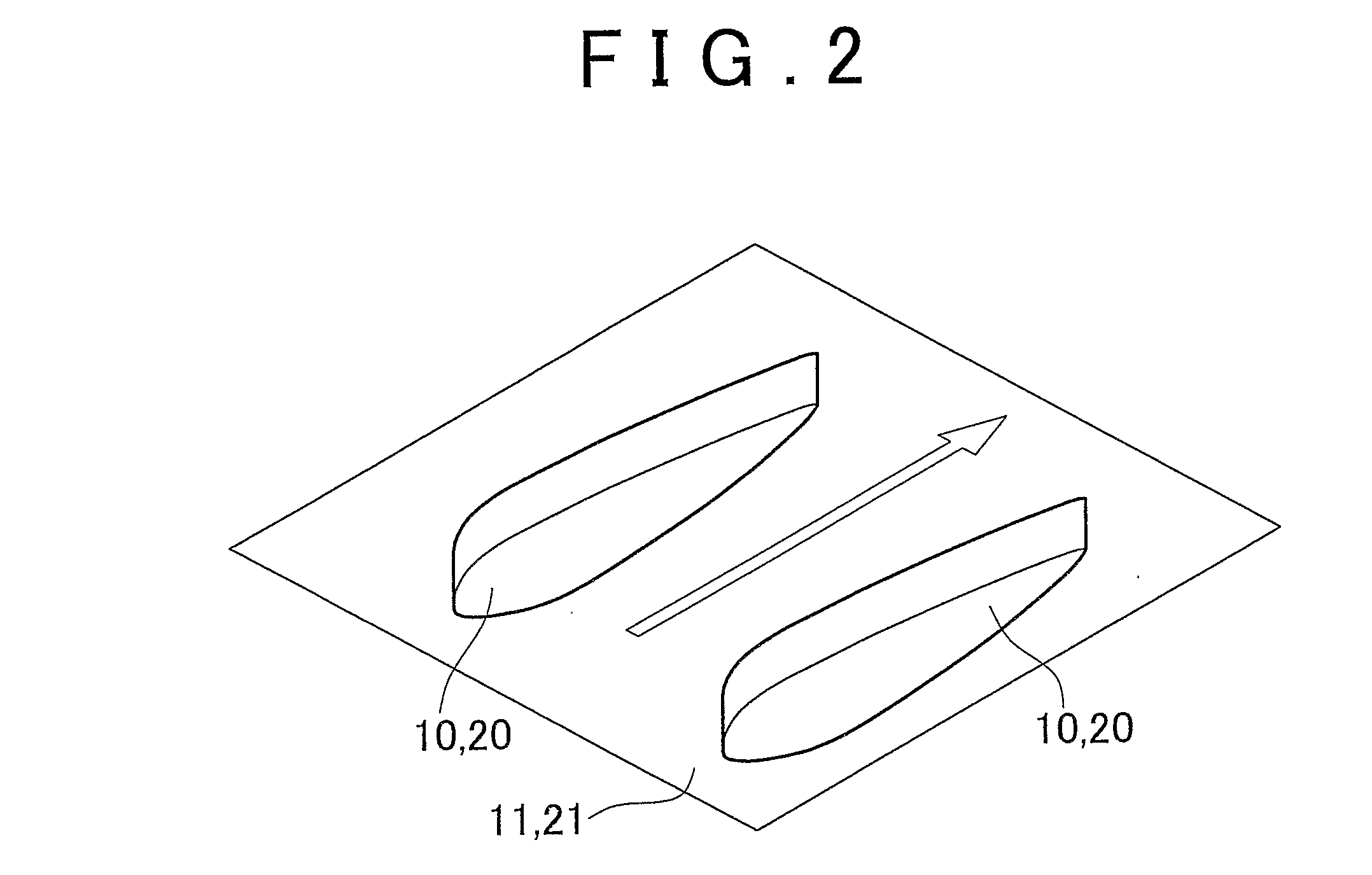
[0021]In this embodiment, the vehicle substructure of the invention is applied to a vehicle substructure of a general automobile. In the vehicle substructure according to this embodiment, two airfoil fins are provided on the vehicle rear side under the floor of a car body. This embodiment consists of two embodiments due to the difference in position to attach the airfoil fins, the first being an embodiment in which the airfoil fins are attached to a rear diffuser, and the second an embodiment in which the airfoil fins are attached to a rear part of a floor cover.

[0022]A vehicle substructure 1 according to the first embodiment is described with reference to FIGS. 1 to 4. FIG. 1 is a side view of a vehicle having the vehicle substructure according to the first embodiment. FIG. 2 is a perspective view of the airfoil fins according to the first embodiment...


PUM


Abstract

A vehicle substructure (1) having a rectifying fin (10) that is attached under the floor of a car body and rectifies a flow of fluid under the floor of the car body, wherein the rectifying fin (10) is an airfoil fin that has a blade thickness in a right-to-left direction of a vehicle.

Description

BACKGROUND OF THE INVENTION[0001]1. Field of the Invention[0002]This invention relates to a vehicle and a vehicle substructure for stabilizing a flow of fluid under the floor of a car body.[0003]2. Description of the Related Art[0004]Without any aerodynamic equipment provided under the floor of a car body, a flow of air under the floor of the car body cannot be stabilized and therefore cannot be diffused smoothly at a rear end of the vehicle. Consequently, stability of the vehicle is deteriorated and air resistance increases. For this reason, there exists a sports car provided with a diffuser at a rear end part of the floor of the car body and with a rectifying fin on a flat plate of the diffuser. Furthermore, in the structure described in Japanese Utility Model Application Publication No. 3-103882 (JP-U-3-103882), an under spoiler is provided horizontally in a lower position of a rear bumper that has a predetermined ventilation gap.[0005]However, in the diffuser and the rectifying ...

Claims


Application Information

Patent Timeline
IPC IPC(8): B62D35/02
CPCB62D35/02Y02T10/82Y02T10/88
Inventor YAMAGISHI, KOUICHIFUJII, NARITOYAMADA, KOUSHIOSADA, SHIGENORI
Owner TOYOTA JIDOSHA KK
Why Eureka
Try Eureka