Plasma display panel

Inactive Publication Date: 2007-11-08
SAMSUNG SDI CO LTD
View PDF3 Cites 4 Cited by
  • Summary
  • Abstract
  • Description
  • Claims
  • Application Information

AI Technical Summary

Benefits of technology

[0013]The present embodiments provide a plasma display panel in which the capacitances of all discharge cells are substantially the same and the same fi

Problems solved by technology

However, intersecting electrodes in the plasma display panel are not generally coated with the same material in all of the discharge cells.
However, an overdischarge can occur in other discharge cells except a discharge cell requiring the highest firi

Method used


Image

  • Plasma display panel
  • Plasma display panel
  • Plasma display panel

Examples


Embodiment Construction

[0029]Hereinafter, exemplary embodiments will be described in detail with reference to the accompanying drawings.

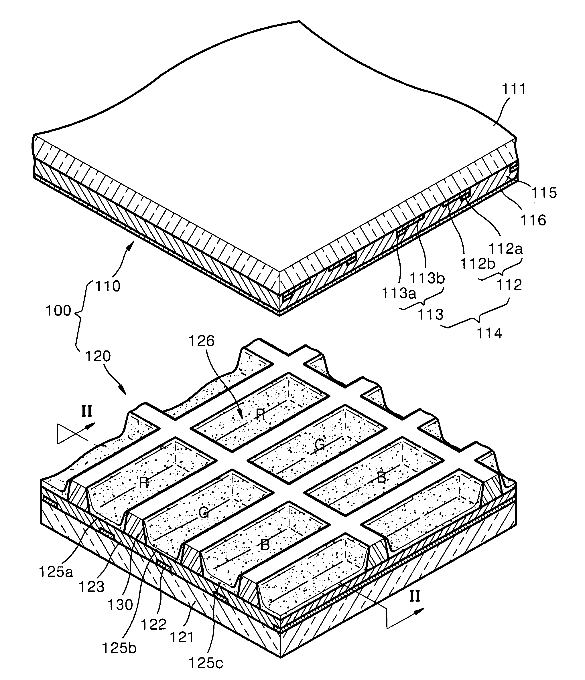
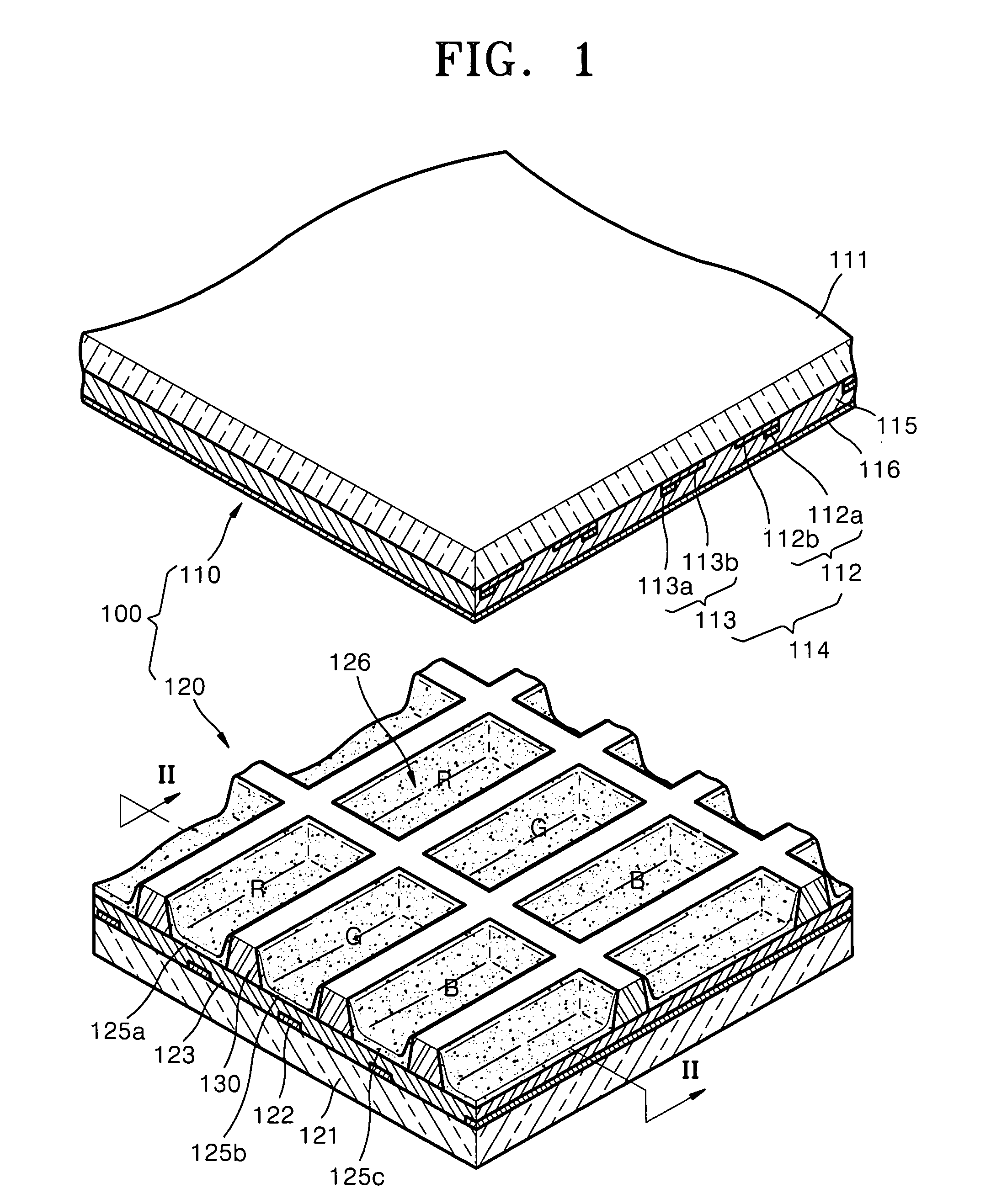
[0030]FIG. 1 is an exploded perspective view of a plasma display panel 100 according to an embodiment. FIG. 2 is a cross-sectional view of the plasma display panel 100, taken along line II-II of FIG. 1.

[0031]Referring to FIGS. 1 and 2, the plasma display panel 100 includes a first panel 110 and a second panel 120.

[0032]The first panel 110 includes a first substrate 111, a plurality of discharge electrodes 114 each having an X electrode 113 and an Y electrode 112 that extend over a plurality of discharge cells 126 and are supported by the first substrate 111, a first dielectric layer 115 covering the X electrode 113 and the Y electrode 112, and a protective layer 116 formed on the first dielectric layer 115.

[0033]The second panel 120 includes a second substrate 121 located to face the first substrate 111 at a predetermined distance from the first substrate 111, address ele...


PUM


Abstract

Provided is a plasma display panel in which the capacitances of all discharge cells are substantially the same and the same firing voltage is applied to the discharge cells, thereby preventing an overdischarge from occurring therein and reducing the firing voltage. The plasma display panel includes a first substrate, a second substrate located to face the first substrate at a predetermined distance from the first substrate, a barrier rib structure located between the first and second substrates to define discharge cells in which a gas discharge occurs, pairs of discharge electrodes each including an X electrode and an Y electrode which extend across the discharge cells, address electrodes extending across the discharge cells to intersect the discharge electrodes in the discharge cells, and phosphor layers each being applied onto one of the discharge cells and formed of one of red, green, and blue emitting phosphors. Here, the thicknesses of the red, green, and blue phosphor layers which are respectively formed in the discharge cells are different from one another.

Description

CROSS-REFERENCE TO RELATED PATENT APPLICATION[0001]This application claims the priority of Korean Patent Application No. 10-2006-0040403, filed on May 4, 2006, in the Korean Intellectual Property Office, the disclosure of which is incorporated herein in its entirety by reference.BACKGROUND OF THE INVENTION[0002]1. Field of the Invention[0003]The present embodiments relate to a plasma display panel, and more particularly, to a plasma display panel having an improved phosphor layer structure.[0004]2. Description of the Related Art[0005]Plasma display panels, which display an image by excitation of phosphor using ultraviolet rays generated by a gas discharge, are considered to be the next-generation display devices due to the possibility to manufacture them using high-definition, large screens.[0006]A plasma display panel includes a first substrate and a second substrate that face each other and are spaced apart a predetermined distance, a barrier rib structure that divides a space bet...

Claims


Application Information

Patent Timeline
IPC IPC(8): H01J17/49
CPCC09K11/595C09K11/7734C09K11/778H01J11/42C09K11/7797H01J11/12C09K11/7787
Inventor KWON, SEUNG-UKJANG, TAE-WOONG
Owner SAMSUNG SDI CO LTD
Why Eureka
Try Eureka