Reinforcement of boney material surrounding a bone implant

a bone implant and boney material technology, applied in the field of prosthetic devices, can solve problems such as ever-present challenges, and achieve the effect of facilitating injection and facilitating injection into boney materials

Inactive Publication Date: 2007-11-08
SDGI HLDG
View PDF25 Cites 74 Cited by
  • Summary
  • Abstract
  • Description
  • Claims
  • Application Information

AI Technical Summary

Benefits of technology

[0004] In one embodiment, a screw having a stem with threads and an inner chamber is implanted in bone. The inner chamber is in fluid communication with the bone through one or more port openings along the stem. A polymeric material is provided in a first state. Energy is applied to the polymeric material to convert the polymeric material to a more fluid second state. The polymeric material in the second state is flowed from the inner chamber through the one or more openings into boney material to provide reinforcement. The polymeric material returns to the first state after placement in the boney material. In one form, the second state is a softer solid phase of the polymeric material relative to a more rigid solid phase of the polymeric material in the first state and/or the second state of the polymeric material is at least partially liquid as opposed to a solid first state of the polymeric material.
[0005] In another embodiment, a screw is structured for implantation into a bone where the screw has a stem with threads and an inner chamber. The inner chamber of the screw is in fluid communication with the bone through one or more ports along the stem. A device is used to heat a polymeric material from a rigid state to a more fluid state. The polymeric material in the more fluid state is flowed from the inner chamber through the ports into the boney material to provide reinforcement.
[0006] In yet another embodiment, a screw is structured to engage bone that includes a head portion, a threaded stem opposite the head portion, and an inner chamber along the stem. The inner chamber is in fluid communication with the bone through one or more ports along the stem. A polymeric material

Problems solved by technology

Nonetheless, there is an ever-present challenge to provide more se

Method used


Image

  • Reinforcement of boney material surrounding a bone implant
  • Reinforcement of boney material surrounding a bone implant
  • Reinforcement of boney material surrounding a bone implant

Examples


Embodiment Construction

[0018] For the purpose of promoting an understanding of the principles of the invention, reference will now be made to the embodiments illustrated in the drawings and specific language will be used to describe the same. It will nevertheless be understood that no limitation of the scope of the invention is thereby intended. Any alterations and further modifications in the described embodiments, and any further applications of the principles of the invention as described herein are contemplated as would normally occur to one skilled in the art to which the invention relates.

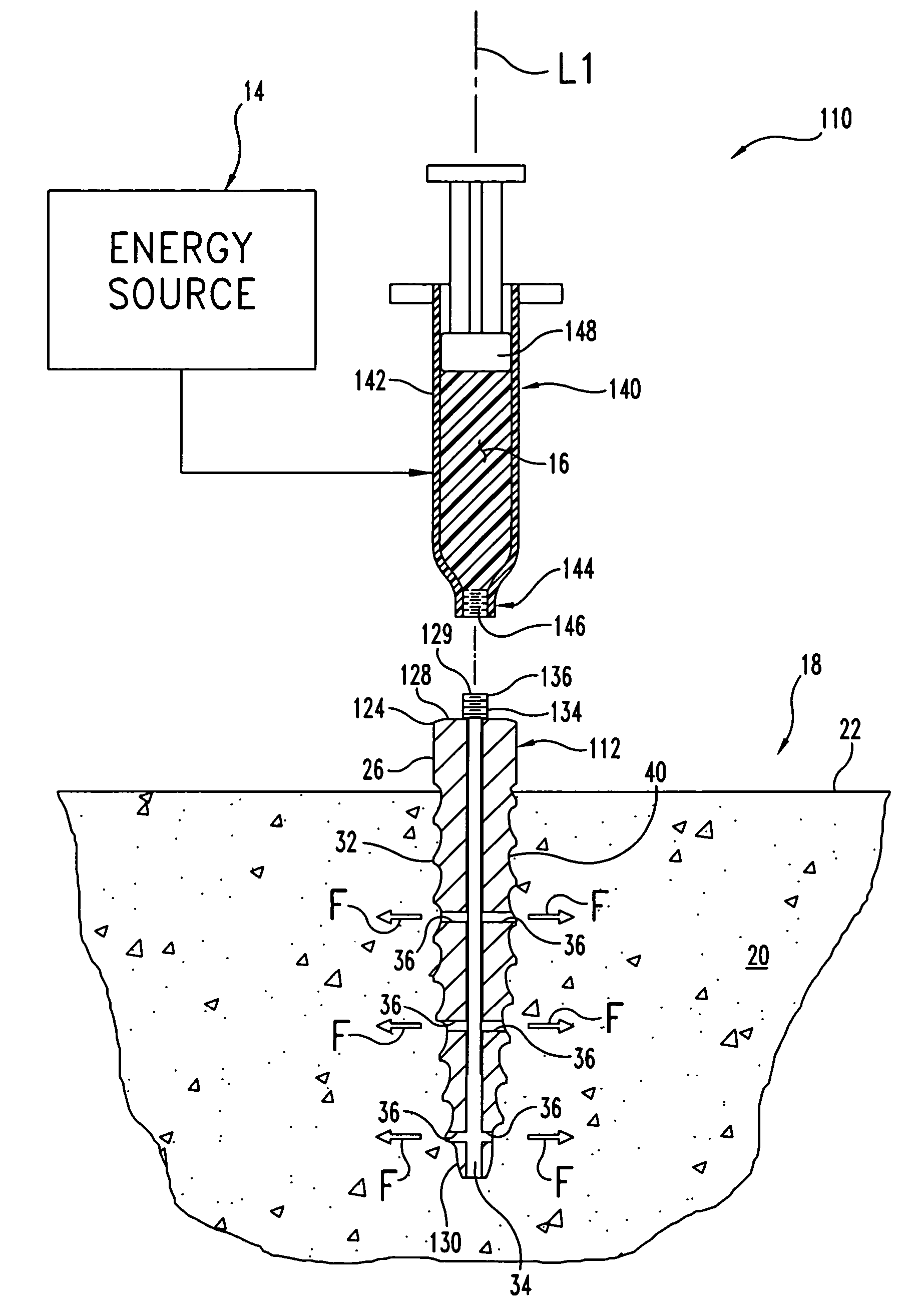
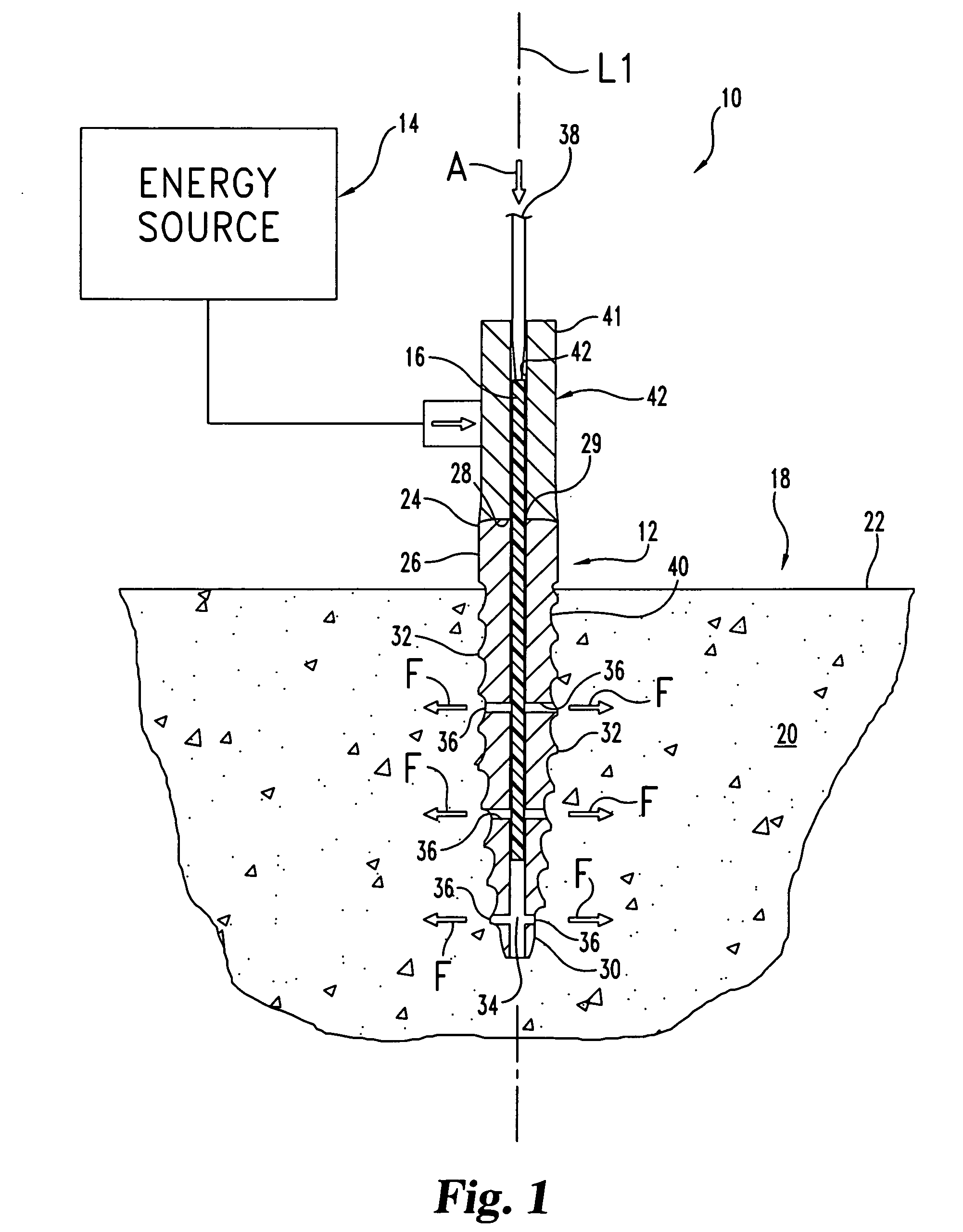
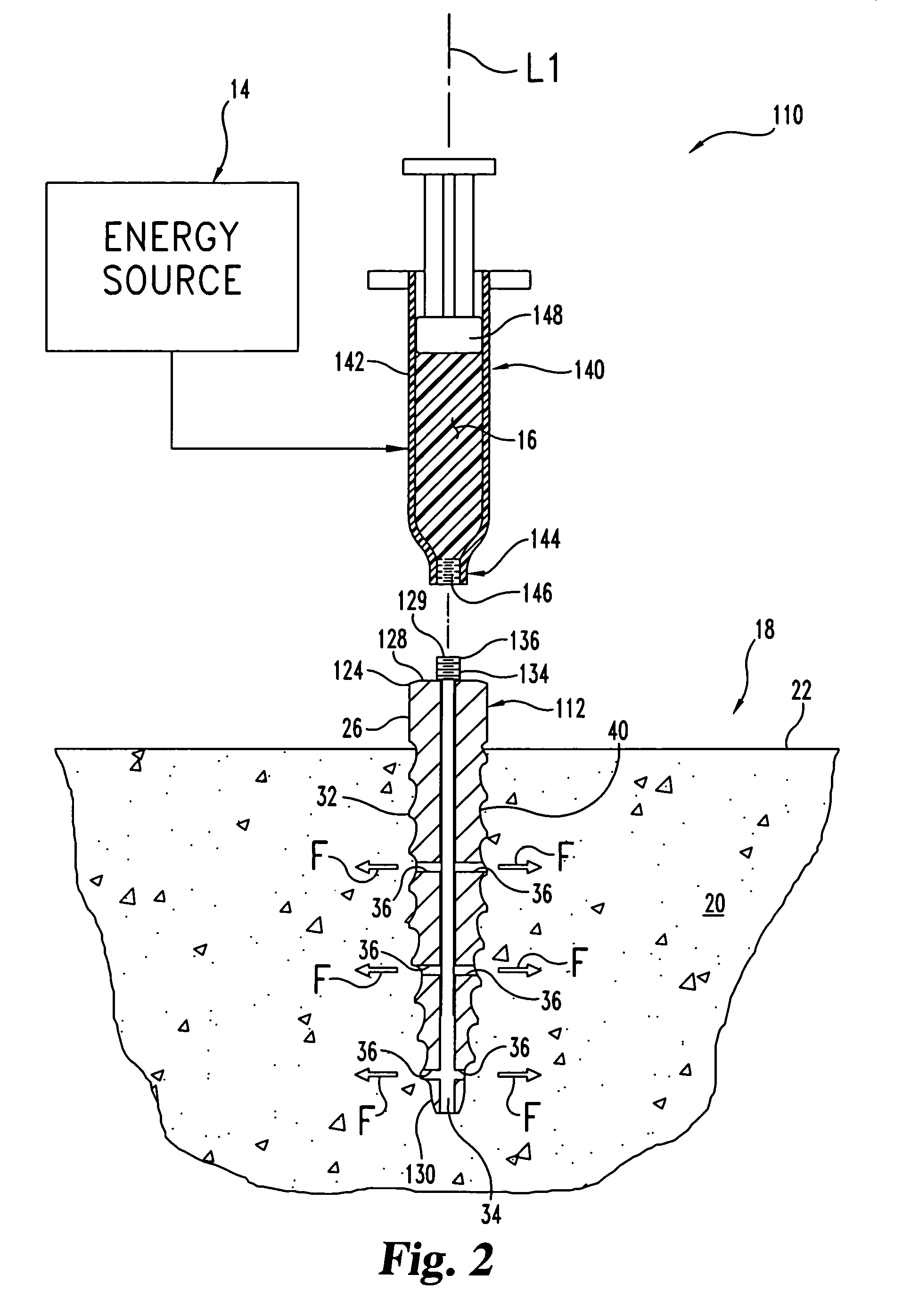
[0019]FIG. 1 depicts a reinforcement system 10 according to one embodiment of the current invention. The reinforcement system 10 comprises a screw 12, an energy source 14, and an organic polymeric material 16. Screw 12 and polymeric material 16 are shown in section, while energy source 14 is represented schematically. The reinforcement system 10 is generally utilized when the screw 12 is implanted into a bone 18. ...


PUM


Abstract

A screw structured to engage bone has a stem with threads and an inner chamber. The inner chamber is in fluid communication with one or more ports along the stem. A polymeric material is provided with the screw. After implantation of the screw in bone, energy is applied to the polymeric material to convert the material to a more fluid form, and while in this form, the polymeric material is flowed from the inner chamber and out through the one or more ports into boney material to provide reinforcement.

Description

BACKGROUND [0001] The present invention relates to a prosthetic device and manner of using the same, and more particularly, but not exclusively, relates to a technique to reinforce bone engaged by an implant. [0002] The use of prosthetic implants to address orthopedic injuries and ailments has become commonplace. Nonetheless, there is an ever-present challenge to provide more secure and reliable implant constructs to improve procedure outcome. Thus, there is a need for additional contributions in this area of technology. SUMMARY [0003] One embodiment of the present application is a unique implantation technique. Other embodiments include unique methods, systems, devices, kits, and apparatus involving an implantable prosthesis. [0004] In one embodiment, a screw having a stem with threads and an inner chamber is implanted in bone. The inner chamber is in fluid communication with the bone through one or more port openings along the stem. A polymeric material is provided in a first stat...

Claims


Application Information

Patent Timeline
IPC IPC(8): A61B17/86
CPCA61B17/7098A61B2017/8655A61B2017/00004A61B17/864A61B17/86A61F2/28A61L27/14
Inventor WISNEWSKI, PAUL J.CHAFFIN, KIMBERLY A.ISTEPHANOUS, NAIMVEGOE, BRETT R.
Owner SDGI HLDG
Why Eureka
Try Eureka