Ultra small microphone array

a microphone array and ultra-small technology, applied in the field of audio signal processing, can solve the problems of increasing the distance between the microphones, the practicable lower limit of the spacing between adjacent microphones, and the inability to use more expensive microphones for certain devices,

Active Publication Date: 2007-11-08
SONY COMPUTER ENTERTAINMENT INC +1
View PDF67 Cites 137 Cited by
  • Summary
  • Abstract
  • Description
  • Claims
  • Application Information

AI Technical Summary

Benefits of technology

[0007] In certain embodiments, one or more fractional delays may optionally be applied to selected input signals xm(t) other than an input signal x0(t) from a reference microphone M0. Each fractional delay may be selected to optimize a signal to noise ratio of a discrete time domain output signal y(t) from the microphone array. The fractional delays may be selected for anti-causality, i.e., selected such that a signal from the reference microphone M0 is first in time relative to signals from the other microphone(s) of the array. In some embodiments, a fractional time delay Δ may optionally be introduced into an output signal y(t) so that: y(t+Δ)=x(t+Δ)*b0+x(t−1+Δ)*b1+x(t−2+Δ)*b2+ . . . +x(t−N+Δ)bN, where Δ is between zero and ±1.

Problems solved by technology

However, there is a practical lower limit to the spacing between adjacent microphones.
Unfortunately, increasing the distance between microphones may not be possible for certain devices, e.g., cell phones, personal digital assistants, video cameras, digital cameras and other hand-held devices.
Improving the dynamic range typically means using more expensive microphones.
Given this limitation on the microphone response, neighboring microphones typically have to be about 4 centimeters (cm) apart.
Such an array would take up much too large a space to be practical in many portable hand-held devices.

Method used


Image

  • Ultra small microphone array
  • Ultra small microphone array
  • Ultra small microphone array

Examples


Embodiment Construction

[0016] Although the following detailed description contains many specific details for the purposes of illustration, anyone of ordinary skill in the art will appreciate that many variations and alterations to the following details are within the scope of the invention. Accordingly, the exemplary embodiments of the invention described below are set forth without any loss of generality to, and without imposing limitations upon, the claimed invention.

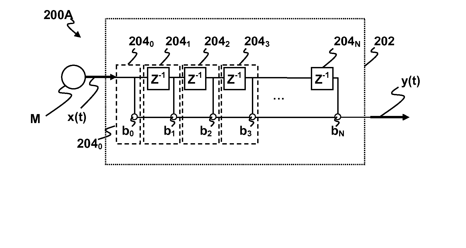
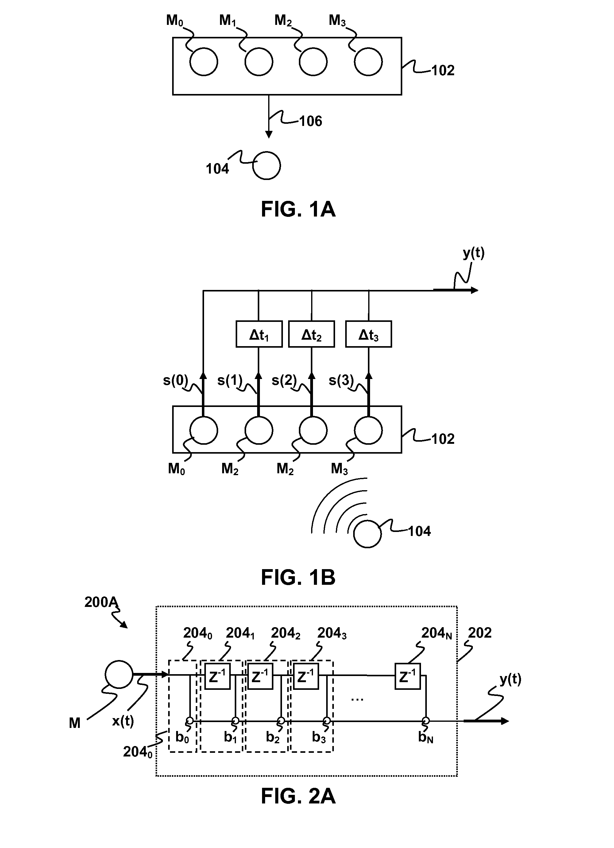
[0017] As depicted in FIG. 1A, a microphone array 102 may include four microphones M0, M1, M2, and M3. In general, the microphones M0, M1, M2, and M3 may be omni-directional microphones, i.e., microphones that can detect sound from essentially any direction. Omni-directional microphones are generally simpler in construction and less expensive than microphones having a preferred listening direction. An audio signal arriving at the microphone array 102 from one or more sources 104 may be expressed as a vector x=[x0, x1, x2, x3], where x0, x1...


PUM


Abstract

Methods and apparatus for signal processing are disclosed. A discrete time domain input signal xm(t) may be produced from an array of microphones M0 . . . MM. A listening direction may be determined for the microphone array. The listening direction is used in a semi-blind source separation to select the finite impulse response filter coefficients b0, b1 . . . , bN to separate out different sound sources from input signal xm(t). One or more fractional delays may optionally be applied to selected input signals xm(t) other than an input signal x0(t) from a reference microphone M0. Each fractional delay may be selected to optimize a signal to noise ratio of a discrete time domain output signal y(t) from the microphone array. The fractional delays may be selected to such that a signal from the reference microphone M0 is first in time relative to signals from the other microphone(s) of the array. A fractional time delay Δ may optionally be introduced into an output signal y(t) so that: y(t+Δ)=x(t+Δ)*b0+x(t−1+Δ)*b1+x(t−2+Δ)*b2+ . . . +x(t−N+Δ)bN, where Δ is between zero and ±1.

Description

CROSS-REFERENCE TO RELATED APPLICATIONS [0001] This application is related to commonly-assigned, co-pending application Ser. No. ______, to Xiao Dong Mao, entitled ECHO AND NOISE CANCELLATION, (Attorney Docket SCEA05064US00), filed the same day as the present application, the entire disclosures of which are incorporated herein by reference. This application is also related to commonly-assigned, co-pending application Ser. No. ______, to Xiao Dong Mao, entitled “METHODS AND APPARATUS FOR TARGETED SOUND DETECTION”, (Attorney Docket SCEA05072US00), filed the same day as the present application, the entire disclosures of which are incorporated herein by reference. This application is also related to commonly-assigned, co-pending application Ser. No. ______, to Xiao Dong Mao, entitled “NOISE REMOVAL FOR ELECTRONIC DEVICE WITH FAR FIELD MICROPHONE ON CONSOLE”, (Attorney Docket SCEA05073US00), filed the same day as the present application, the entire disclosures of which are incorporated h...

Claims


Application Information

Patent Timeline
Patent Type & Authority Applications(United States)
IPC IPC(8): G06F17/00
CPCH04R1/406H04R2201/401H04R3/005
Inventor MAO, XIADONG
Owner SONY COMPUTER ENTERTAINMENT INC
Why Eureka
Try Eureka