Double Floor with Decorative Plate

Inactive Publication Date: 2007-11-15
FREE AXEZ
View PDF13 Cites 1 Cited by
  • Summary
  • Abstract
  • Description
  • Claims
  • Application Information

AI Technical Summary

Benefits of technology

[0012]Since the double floor with a decorative plate of the present invention has been constituted as explained above, the following advantages can be obtained:
[0013]1. Since a double floor with a woody decorative plate attached on a steel-made base provides a relaxed atmosphere to the eye and presents graceful atmosphere, it is optimal to lay the double floor in, especially, a reception room or an executive suite.
[0015]3. Accordingly, such an object that wires can be drawn out of relatively free positions, while exclusive air is being maintained, which is difficult to achieve in the conventional double floor with a decorative plate, can be achieved.

Problems solved by technology

1. It is desired to draw a wire arranged below the double floor out of an arbitrary position as much as possible according to arrangement of business disk and equipment.
2. In that case, when the double floor is a steel-made one, it is relatively easy to provide a small opening for drawing out a wire at an arbitrary position.
3. However, when a woody decorative plate is attached on a steel-made base, it is difficult to notch the woody decorative plate and the steel plate simultaneously, which results in loss in flexibility for drawing out a wire such as obtained in the steel-made double floor.
4. Thus, the double floor obtained by attaching a woody decorative plate on a steel-made base provides a relaxed atmosphere to the eye and presents graceful atmosphere but it includes such a problem that it is difficult to draw a wire out of an arbitrary position.

Method used


Image

  • Double Floor with Decorative Plate
  • Double Floor with Decorative Plate
  • Double Floor with Decorative Plate

Examples


embodiment

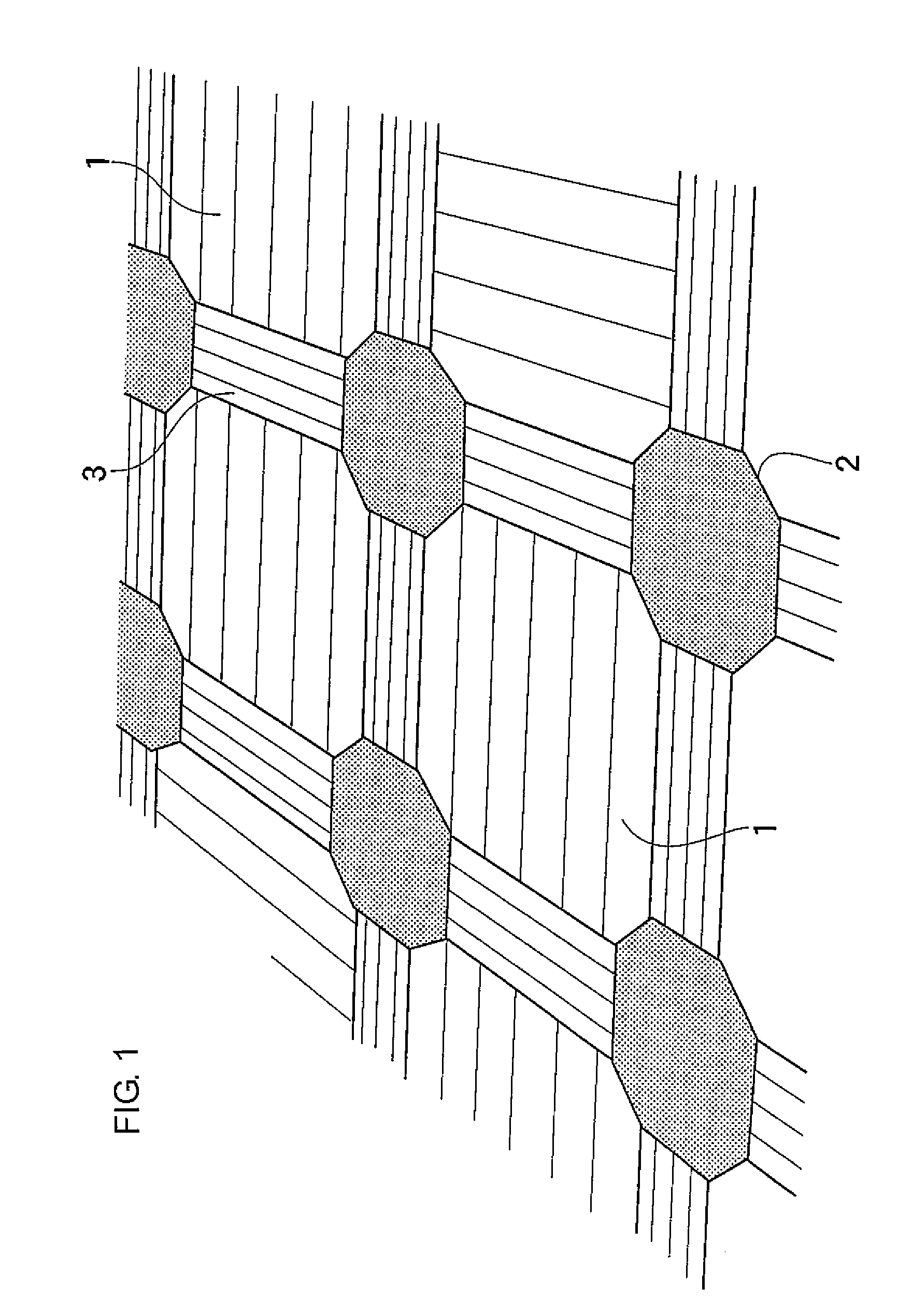
[0024]1. Whole Constitution (See FIG. 1)

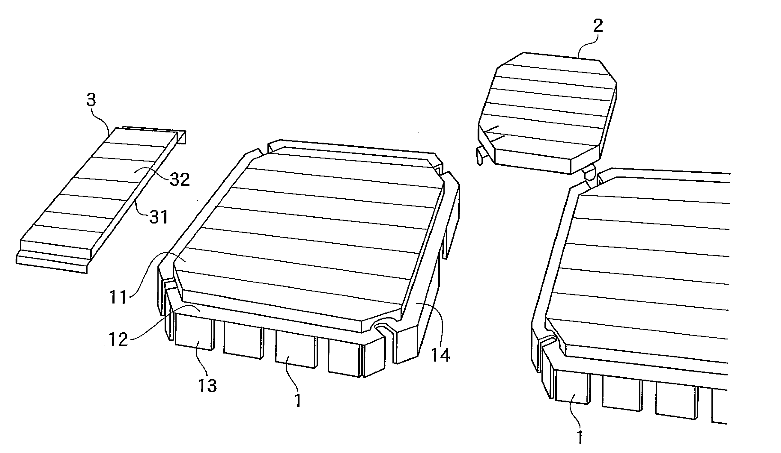
[0025]A double floor of the present invention is constituted of base units 1, corner plates 2, and channel plates 3. A double floor can be spaced from an original floor face by a predetermined distance by combining these members to lay them on the floor face.

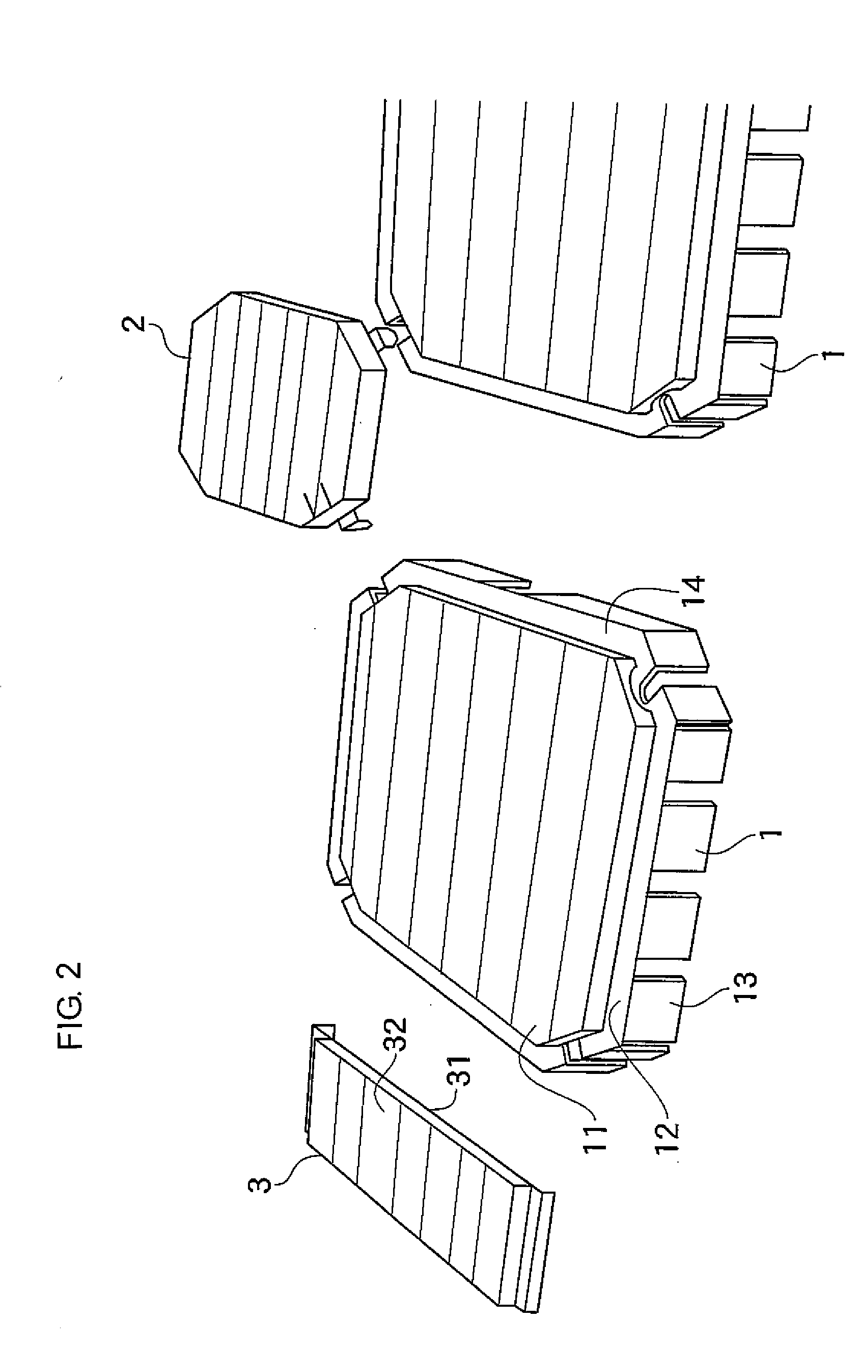
[0026]2. Base Unit 1 (See FIG. 2)

[0027]Each base unit 1 includes a steel-made base, where a woody decorative plate 11 is attached on a surface of the steel-made base.

[0028]The steel-made base is constituted of an octagonal steel-made top plate 12 formed by cutting corner portions of a square plate, and leg plates 13 provided around the top plate 12.

[0029]The leg plates 13 are plates serving as legs of the top plate 12.

[0030]A surface of the double floor is disposed at a position higher than an original floor face by a height of the leg plates 13.

[0031]The steel-made top plate 12 and the woody decorative plate 11 are not the same in size, but both plates are similar, where the woody decorat...


PUM


Abstract

A double floor with a decorative plate includes a base unit, a corner plate, and a channel plate that are each made of a steel plate, a surface of the steel plate being attached with a woody decorative plate. A claw projecting outside the decorative plate is formed on a face of the corner plate contacting with the base unit by extending one portion of the steel plate. Two cutoff lines are formed in a portion of the decorative plate contacting with the claw in a cutting manner. The claw of the steel plate and a portion of the decorative plate defined between the two cutoff lines can be removed according to necessity.

Description

BACKGROUND OF THE INVENTION[0001]1. Field of the Invention[0002]The present invention relates to a double floor with a decorative plate.[0003]2. Description of the Related Art[0004]Here, the term “double floor” means a structure for applying a double floor to an original floor face to accommodate wires below the double floor, namely, between the double floor and the original floor face, in order to arrange wires for a computer and the like below the double floor.[0005]Many kinds of structures have been developed for the double floor, and such a double floor whose surface is attached with a woody decorative plate to provide a relaxed atmosphere to indoor has been developed. One example of the related arts is disclosed in the Japanese unexamined patent publication No. JP-2003-3654A.[0006]A double floor with decorative plate attached with a woody decorative plate such as described above includes the following problems:[0007]1. It is desired to draw a wire arranged below the double floo...

Claims


Application Information

Patent Timeline
IPC IPC(8): E04B2/08
CPCE04F15/02411E04F15/041E04F15/02194E04F15/06
Inventor GABAKI, KOJI
Owner FREE AXEZ
Why Eureka
Try Eureka