
Stackable mold for making block ice

a block ice and mold technology, applied in the field of block ice molds, can solve the problems of ice melting on the outer surface, ice melting on the outside surface, and the inability to remove the solid block of ice from the container, and achieve the effect of facilitating efficient freezing of water and adding strength

Inactive Publication Date: 2007-11-15
MCDERMOTT CARLOS TOMAS JR
View PDF30 Cites 27 Cited by
  • Summary
  • Abstract
  • Description
  • Claims
  • Application Information

AI Technical Summary

Benefits of technology

[0018] It is another object of the present invention to provide a novel mold that can be stacked directly on top of another mold.
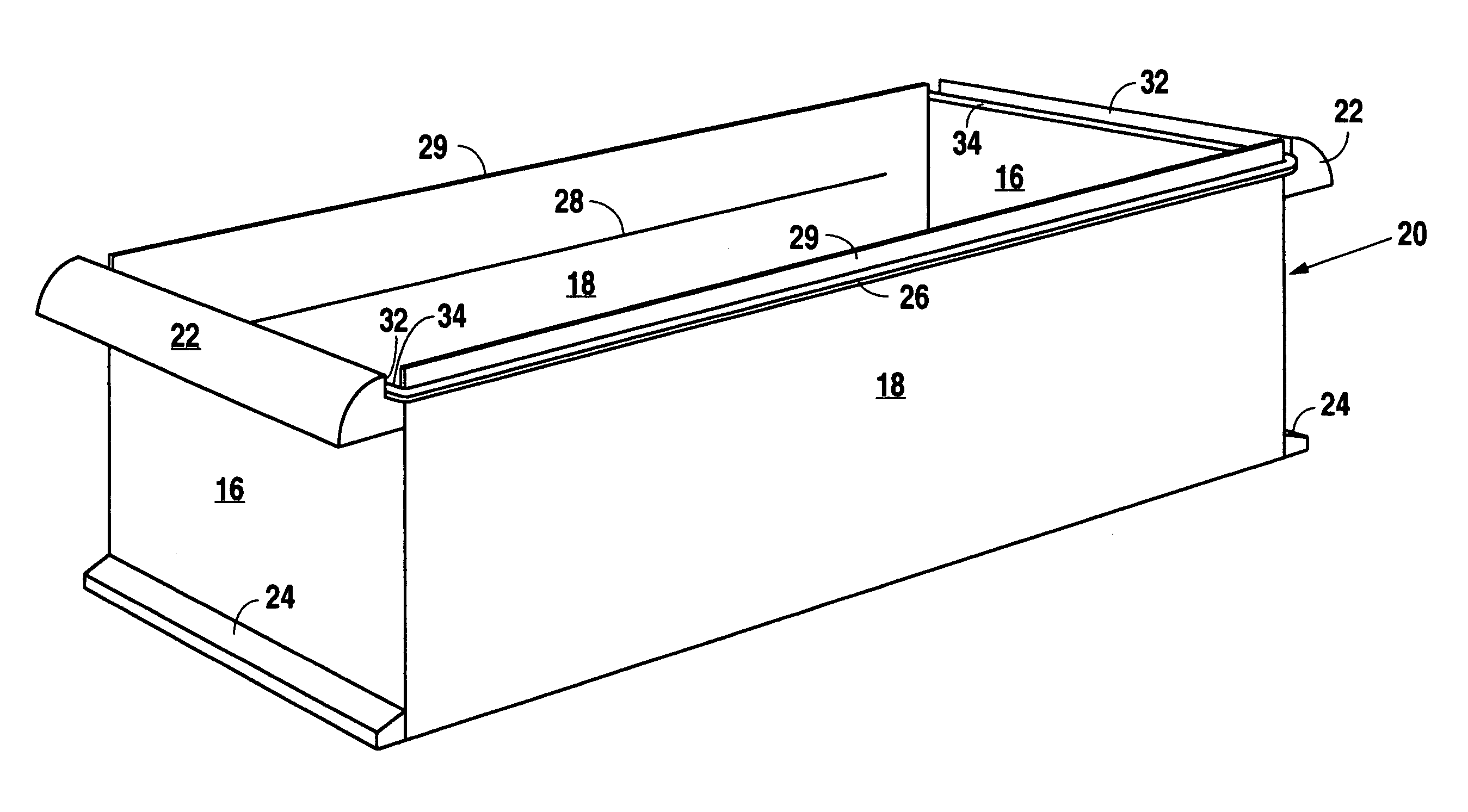
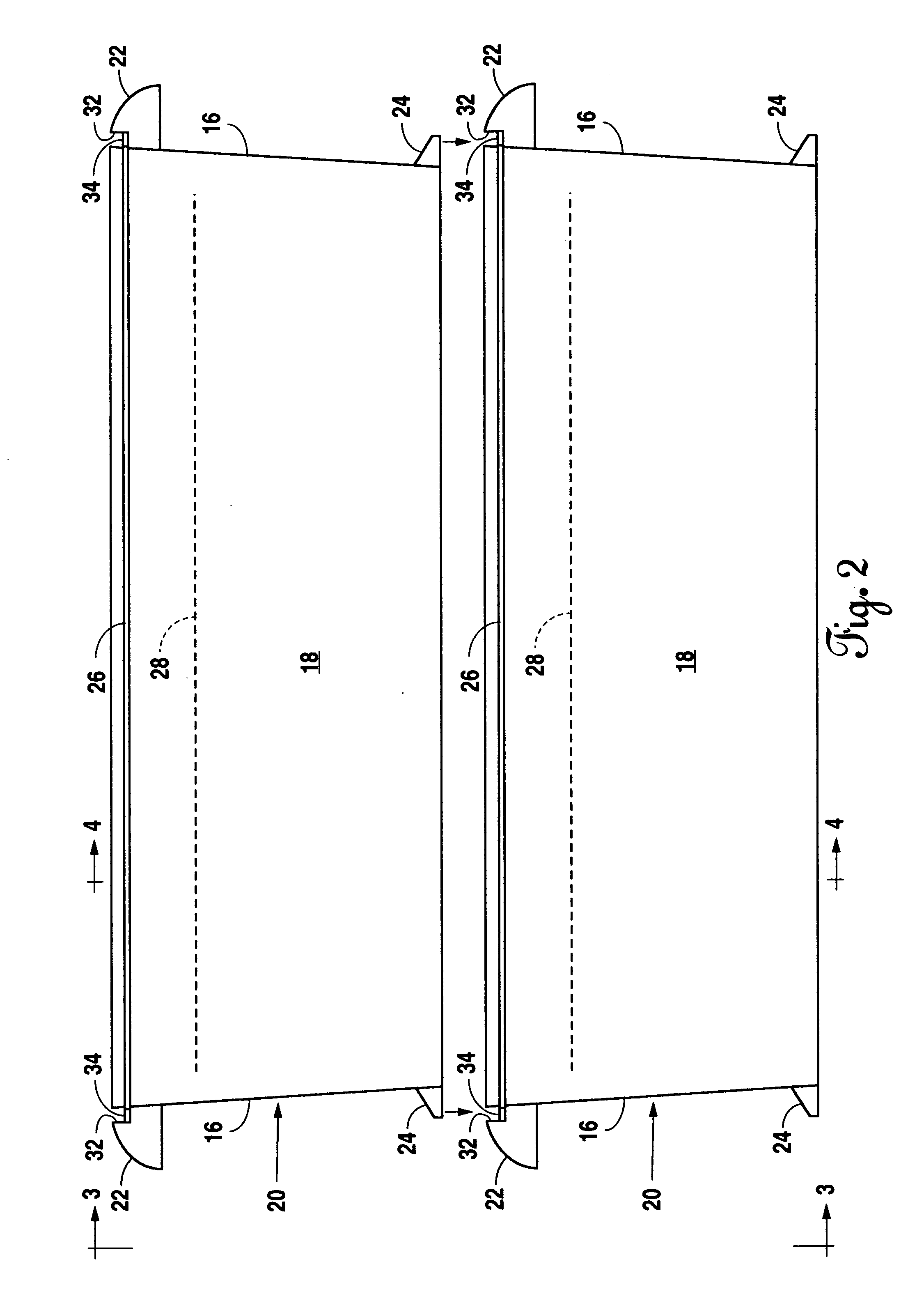
[0030] The stacking lips of an upper mold mate and rest on the stacking ledges on the short sides of a lower mold, thereby allowing the stacking of multiple molds. Due to the tapering of the mold, an air gap is created between the upper edges of the long sides of the lower mold, and the lower edges of the long sides of the upper mold. This allows air to flow through the lower mold.

Problems solved by technology

The common problem associated with the use of ice cubes in an ice chest is that the ice melts rapidly due to the small size of the ice cubes.
This obviously can cause a variety of problems.
Due to the unique shape of these containers, once the water is frozen inside the container, it is impossible to remove the solid block of ice from the container.
One problem associated with making block ice with such containers is that ice melts on its outer surface.
Furthermore, due to the fact that water expands as it freezes, these containers can easily break either while the water is freezing, or if dropped or mishandled during transportation.
When the plastic container is broken, it can create sharp surfaces that may injure the handler.
Moreover, due to the large size of commercial molds, the freezing time in these containers is considerably lengthy.
The molds are also not stackable and cannot be used in a residential setting.
One such mold employs a cumbersome rack and floor panel system to stack multiple molds.
The prior art does not allow for multiple molds to be stacked directly on top of one another.

Method used


Image

  • Stackable mold for making block ice
  • Stackable mold for making block ice
  • Stackable mold for making block ice

Examples


Embodiment Construction

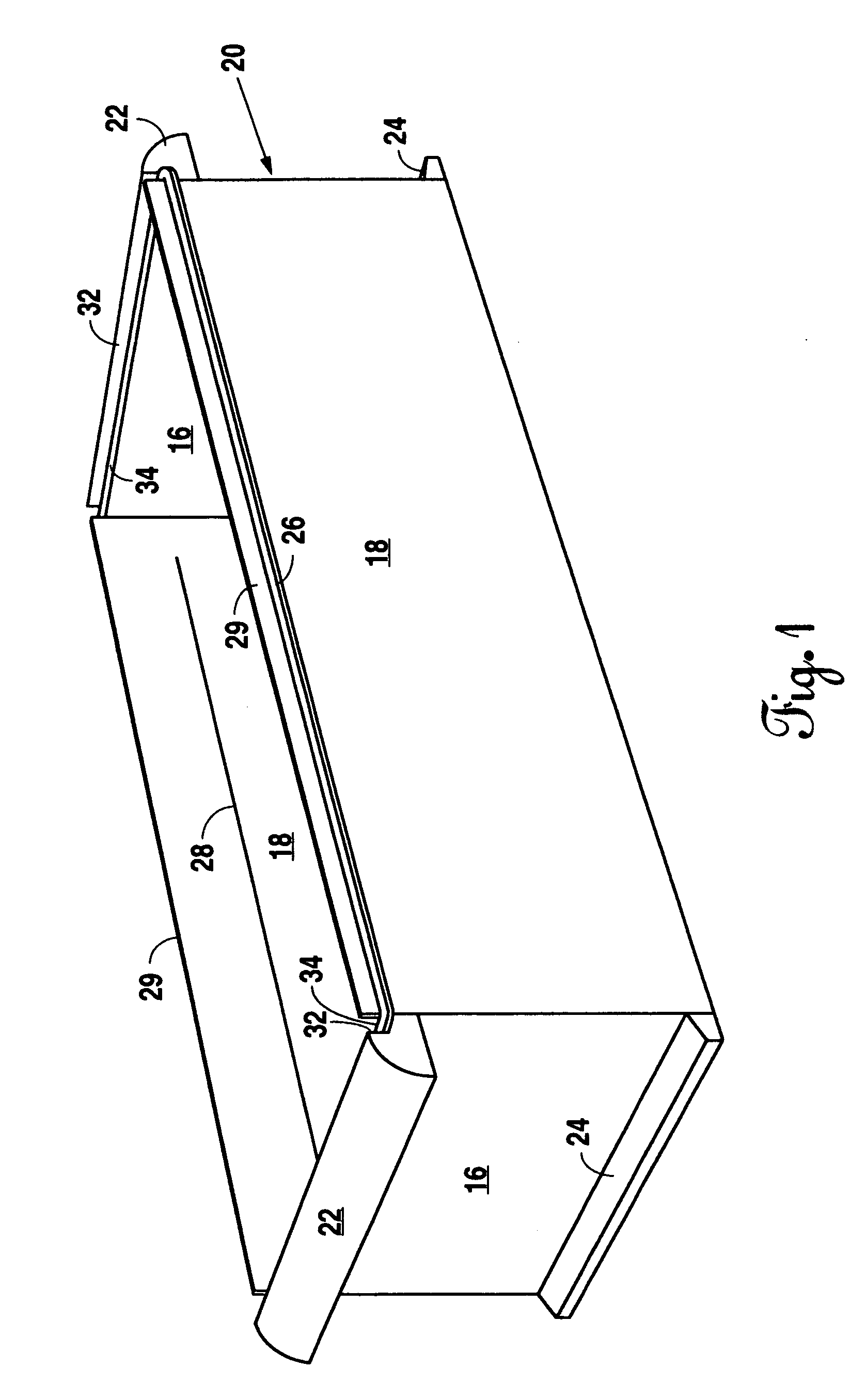
[0037] Referring to FIG. 1, the preferred embodiment for a stackable mold 20 for making block ice is disclosed. Multiple molds 20 can be stacked directly on top of one another. The mold 20 has a bottom and a sidewall. In one embodiment the sidewall is comprised of panels. The panels form a generally rectangularly shaped mold 20, with two parallel long sides 18, and two parallel short sides 16. However, the sidewall can take other shapes, such as rounded or generally oval. The bottom surface (not shown) of the mold 20 is flat. The mold 20 has an open top.

[0038] Handles 22 are located along the top edges of the short sides 16 of the sidewalls of the mold 20. Stacking lips 24 are located along the bottom edges of the short sides 16. Guide lips 32 and 29 are located on the top of the mold 20. The guide lips 29 are located on the long sides 18. The guide lips 32 are located along the short sides 16.

[0039] The mold 20 of the preferred embodiment is tapered toward the bottom, as best sho...


PUM


Abstract

A stackable mold for making block ice is disclosed. The bottom edges of the sidewall of the mold have stacking lips and the top edges of the sidewall have stacking ledges. The stacking ledges of a lower mold mate with the stacking lips of an upper mold, thereby allowing multiple molds to be stacked on top of one another. Guide lips along the sidewalls of the mold prevent slipping and shifting of the stacked molds. The tapered property of the molds creates space between the bottom of an upper mold and the top of a lower mold to allow airflow through the lower mold. A reinforcing lip extends along the top of the long sides for reinforcement.

Description

BACKGROUND OF THE INVENTION [0001] 1. Field of the Invention [0002] Applicant's invention relates to the field of ice molds, and more specifically to a block ice mold that is stackable directly on another like block ice mold. In one embodiment of the invention, the mold is of appropriate size to be placed in a residential freezer. [0003] 2. Background Information [0004] It is common for people to use ice chests or coolers to keep food, beverages, or other items cold for extended periods of time where there is no access to a refrigerator or freezer. Whether on a camping trip, river trip, picnic, or a trip to the lake or beach, people pack their food, drinks, and other various items in their ice chests before heading out on their adventures. Most people use ice cubes from their freezer, or buy bags of ice from the store to keep the food and drink cold. [0005] The common problem associated with the use of ice cubes in an ice chest is that the ice melts rapidly due to the small size of ...

Claims


Application Information

Patent Timeline
IPC IPC(8): B28B7/24
CPCF25C1/22F25C2500/08F25C2500/06F25C2500/02
Inventor MCDERMOTT, CARLOS TOMAS JR.
Owner MCDERMOTT CARLOS TOMAS JR
Learn More