Two-part back cap for a plug valve and plug valves incorporating same

a plug valve and back cap technology, applied in the direction of valve details, valve housings, valve arrangements, etc., can solve the problems of o-ring 34/b> can be damaged, valve leakage around the back cap, etc., to achieve reliable high-pressure seals and easy and reliably installed

Active Publication Date: 2007-11-15
WELLS FARGO BANK NAT ASSOC +1
View PDF25 Cites 2 Cited by
  • Summary
  • Abstract
  • Description
  • Claims
  • Application Information

AI Technical Summary

Benefits of technology

[0008] It is therefore an object of the invention to provide a back cap for a high-pressure plug valve that is easily and reliably installed and provides a long service life without maintenance. It is a further object of the invention to provide a plug valve with a back cap that consistently provides a reliable high-pressure seal.
[0009] The invention therefore provides a two-part back cap for a plug valve, comprising: a back cap seal body having a seal rim that includes at least one O-ring groove that accepts an O-ring for providing a fluid seal between the back cap seal body and a plug valve body of the plug valve; and a back cap retainer nut having pin threads that threadedly engage box threads in the plug valve body for securely retaining the back cap seal body within the plug valve body.
[0010] The invention further provides a plug valve, comprising: a back cap seal body having an inner end with a plug support surface for supporting a plug of the plug valve and an outer end supported by a back cap retainer nut; and the back cap retainer nut comprises a hollow nut having an inner end for supporting the outer end of the back cap seal body and pin threads for engaging box threads in a plug valve body of the plug valve to securely retain the back cap seal body within the plug valve body.

Problems solved by technology

Consequently, the O-ring 34 can be damaged, or it may roll partially out of the O-ring groove 32.
If this occurs the valve will leak around the back cap, even though the leak may not develop until the valve has seen a certain amount of high-pressure service.
That stress eventually causes the O-ring 34 to fail, which results in a leak around the back cap 20, requiring maintenance of the plug valve 10.

Method used


Image

  • Two-part back cap for a plug valve and plug valves incorporating same
  • Two-part back cap for a plug valve and plug valves incorporating same
  • Two-part back cap for a plug valve and plug valves incorporating same

Examples


Embodiment Construction

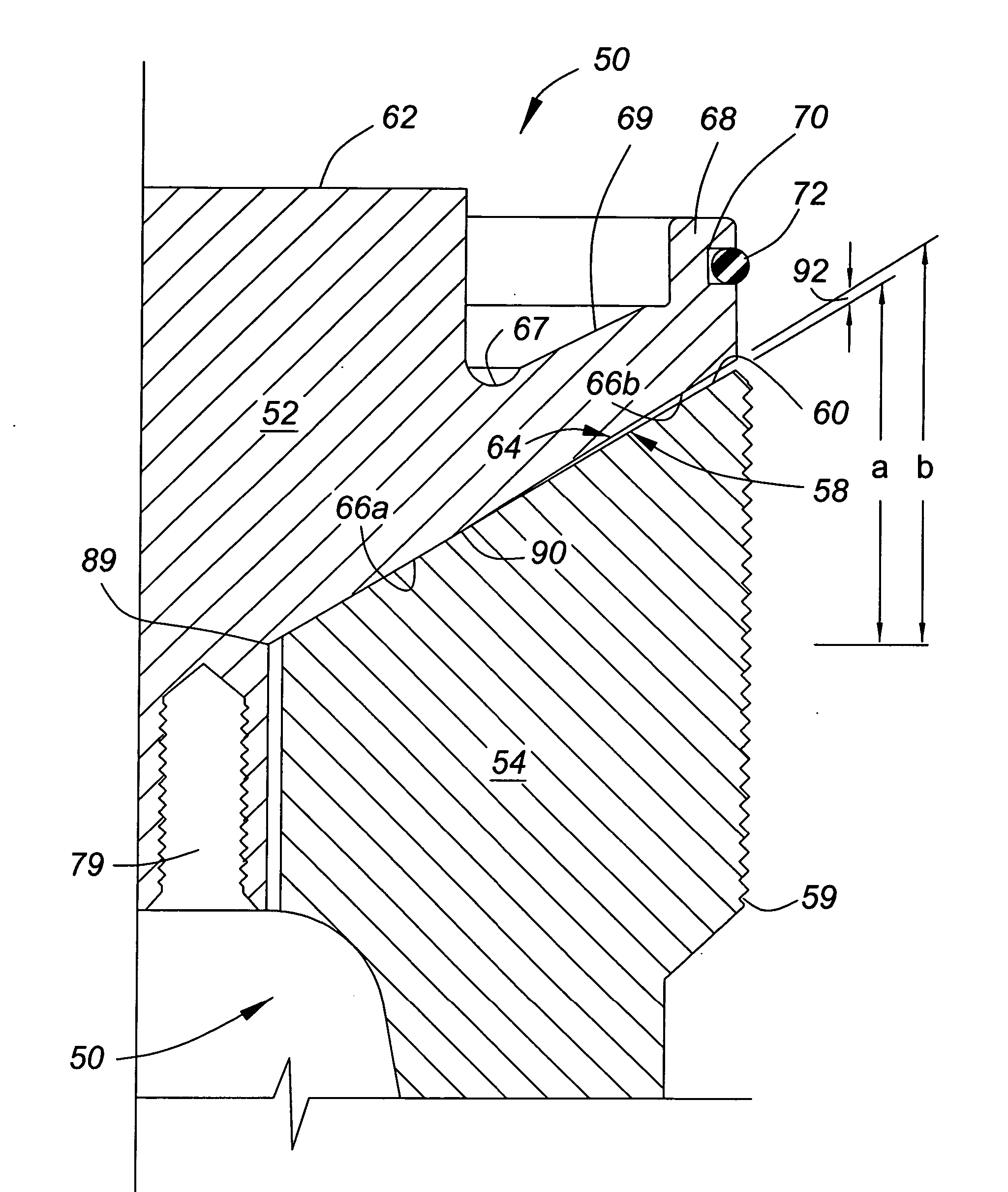
[0020] The invention provides two-part back cap for a plug valve that provides a reliable long-term seal without maintenance. The two-part back cap includes a back cap seal body that can be inserted into a plug valve body without rotation to ensure that an O-ring seal between the back cap seal body and the plug valve body is not damaged during installation of the back cap seal body. The two-part back cap also includes a hollow retainer nut that securely retains the back cap seal body in position. An outer end of the back cap seal body is contoured to provide a gap between an outer edge of the back cap seal body and an inner end of the back cap retainer nut. That gap permits the back cap seal body to expand under fluid pressure along with the plug valve body, ensuring that the O-ring seal is not stressed to when the plug valve is subjected to high fluid pressures. A long service life of the two-part back cap is thereby ensured.

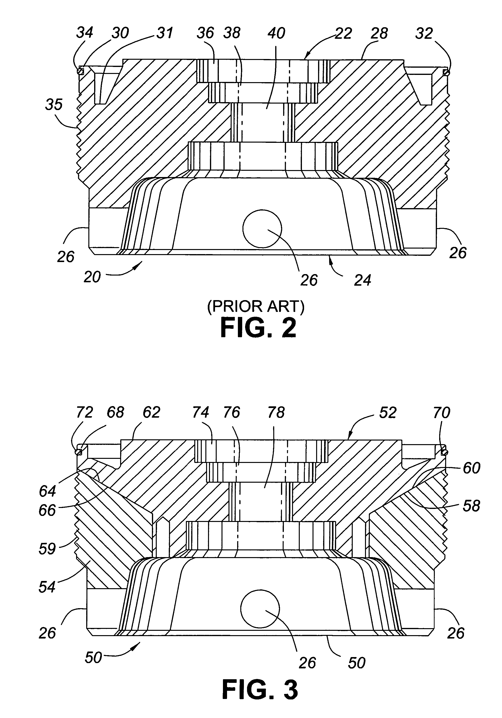
[0021]FIG. 3 is a cross-sectional view of a two-part bac...


PUM


Abstract

A two-part back cap for a plug valve includes a back cap seal body and a back cap retainer nut. The back cap retainer nut secures the back cap seal body within the plug valve and securely supports the back cap seal body. A gap between an outer periphery of the back cap retainer nut and the back cap seal body permits the back cap seal body to flex and expand with a plug valve body of the plug valve. This ensures that the back cap seals are not stressed and a longer service life results.

Description

FIELD OF THE INVENTION [0001] This invention generally relates to fluid flow control valves and, in particular, to back caps for high-pressure plug valves. BACKGROUND OF THE INVENTION [0002] High-pressure plug valves are well known in the art and used principally in the oil and gas industry. A high-pressure plug valve is described in Assignee's co-pending United States Patent Application published under publication number 2006 / 0027779 on Feb. 9, 2006, which is entitled High-Pressure Plug Valve with Replaceable Inserts and Method of Refurbishing Same. [0003]FIG. 1 shows a side elevational view of a plug valve 10 of this type. The plug valve 10 includes a plug valve body 12 having a top flange 14 and a stud pad 16. As will be understood by those skilled in the art, the flange 14 and stud pad 16 could be any of a flange, stud pad or threaded union. The plug valve 10 has a stem 18 for rotating a plug (not shown) within the plug valve body 12 to control fluid flow through the valve in a ...

Claims


Application Information

Patent Timeline
Patent Type & Authority Applications(United States)
IPC IPC(8): F16K5/00
CPCF16K27/067F16K5/0663Y10S251/90
Inventor ARTHERHOLT, DANNY LEE
Owner WELLS FARGO BANK NAT ASSOC
Why Eureka
Try Eureka