High Pressure Injection Arrangement for an Internal Combustion Engine with Direct Injection

a technology of high pressure injection and internal combustion engine, which is applied in the direction of combustion engines, fuel injection apparatus, charge feed systems, etc., can solve the problem that a large portion of the momentum in the spring element is already consumed, and achieve the effect of simple and reliable mounting of the support elemen

Active Publication Date: 2010-01-14
AUDI AG
View PDF22 Cites 9 Cited by
  • Summary
  • Abstract
  • Description
  • Claims
  • Application Information

AI Technical Summary

Benefits of technology

[0012]In another embodiment, the support element is a cage element. Thus, it is meant that the support element encompasses the injection valve at least in certain areas. In particular, it is provided to design the cage element such that the support element has a seat ring that locks in support element holding devices of the injection valve, for example, with clips or clip arms that are extended on the cage element on the outside in the axial direction of the injection valve. Thus, a very simple and reliable mounting of the support element on the injection valve can be achieved; in particular, the injection valve can be preassembled with the support element and the spring washer or the spring element stored therein and is thus available as a subassembly for installation in the internal combustion engine.

Problems solved by technology

In this way, a considerable portion of the momentum in the spring element is already consumed.

Method used


Image

  • High Pressure Injection Arrangement for an Internal Combustion Engine with Direct Injection
  • High Pressure Injection Arrangement for an Internal Combustion Engine with Direct Injection
  • High Pressure Injection Arrangement for an Internal Combustion Engine with Direct Injection

Examples


Embodiment Construction

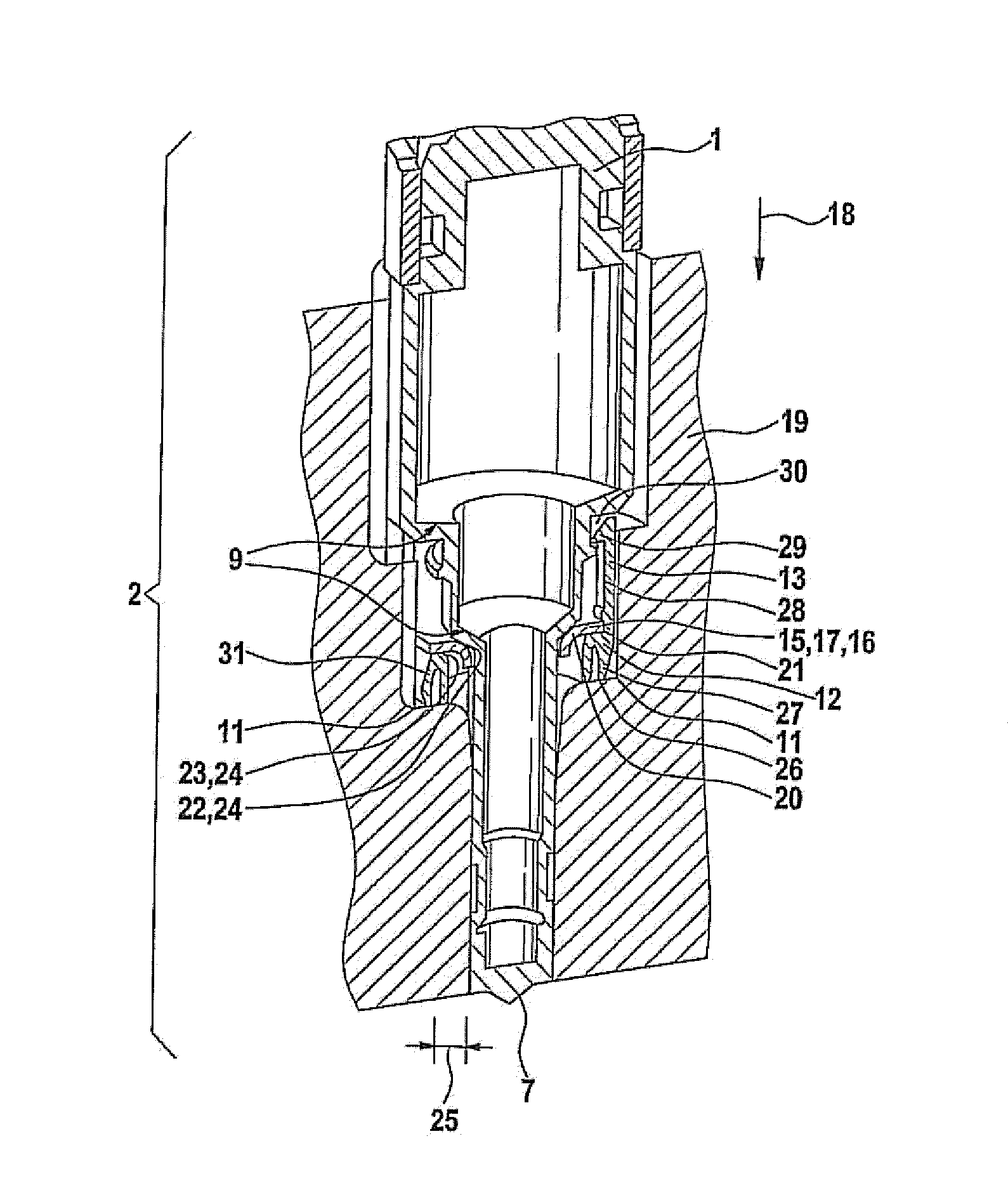
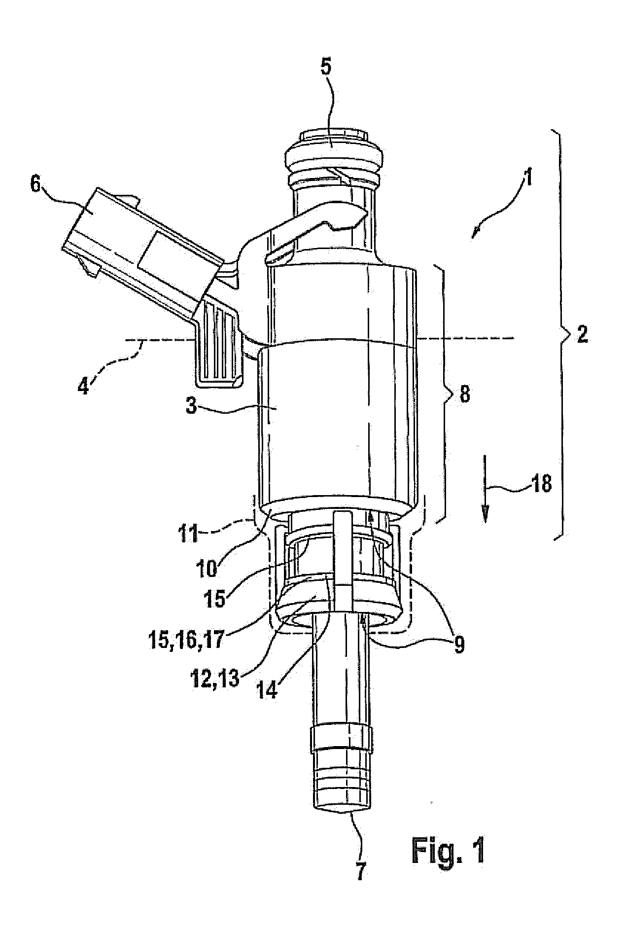
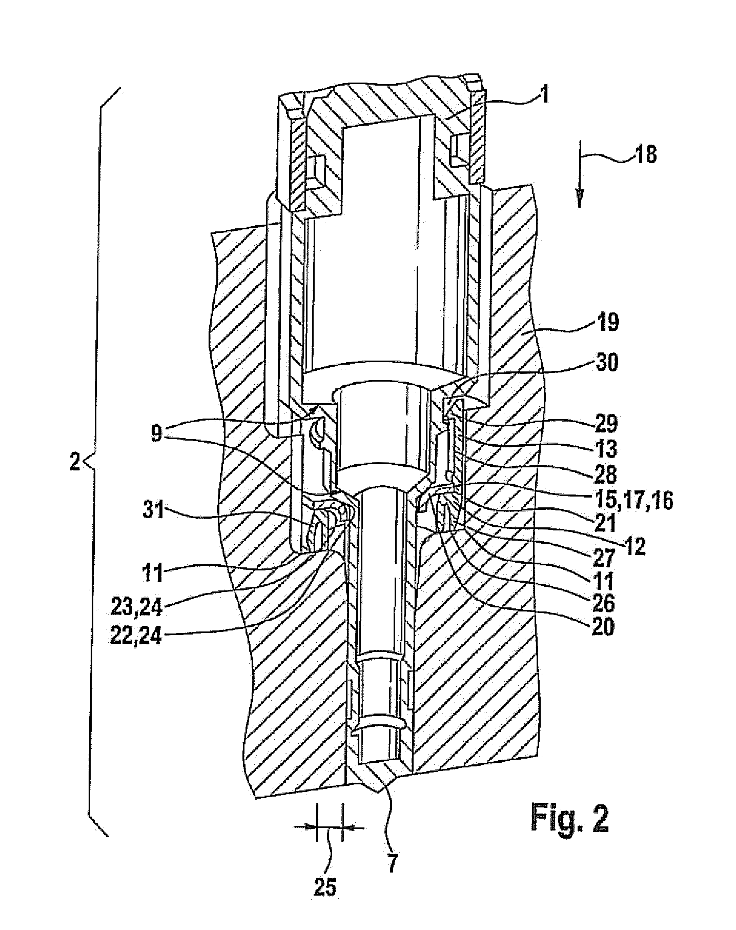
[0015]FIG. 1 shows an injection valve 1 for a high pressure injection unit of a motor vehicle, not shown, with a housing 3 that is designed as a stepped cylinder 2 in the broadest sense, and said housing is used in, for example, a belt line 4 in an engine of an internal combustion engine, not shown, in particular in the area of a cylinder head (not shown in FIG. 1). Above the belt line 4, the injection valve I has a fuel connection 5 as well as an electric connection 6 for connection to the fuel supply and control system of the motor vehicle. The housing 3 is tapered on the end that faces away from the fuel connection 5, in multiple stages up to the formation of an injection nozzle 7, which introduces the fuel to be injected into the combustion chamber of the internal combustion engine. In this connection, the housing 3 can be divided into the valve base 8 and then, toward the injection nozzle, two ring stages 9 for forming the stepped cylinder 2, whereby the ring stages 9 have supp...


PUM


Abstract

The invention relates to a high pressure injection arrangement for an internal combustion engine with direct injection, with an injection valve and a support element, which supports the injection valve in the installed state on a seat of an internal combustion engine. It is provided that a spring element is arranged between the injection valve and the support element.

Description

[0001]The invention relates to a high pressure injection arrangement for an internal combustion engine with direct injection with an injection valve and a support element, which supports the injection valve in the installed state on a seat of an internal combustion engine.BACKGROUND OF THE INVENTION[0002]High pressure injection arrangements of internal combustion engines with direct injection, which have injection valves based on solenoid valve technology, develop high momenta during operation by the solenoid striking its end stops when the valve opens and closes, momenta that are transferred via the housing of the injection valve and the support element to the internal combustion engine and thus result in a noise emission that is perceptible by humans. In particular by reflection of free, oscillating surfaces in or on the cylinder head of the internal combustion engine, thus excited sound pulses that are very readily perceptible by humans are emitted. Because of the high opening an...

Claims


Application Information

Patent Timeline
Patent Type & Authority Applications(United States)
IPC IPC(8): F02B75/00F02M61/14
CPCF02M61/14F02M55/04
Inventor HOEFNER, DIRK
Owner AUDI AG
Why Eureka
Try Eureka