Pipe interruption fitting

a technology of pipe interruption and fitting, which is applied in the direction of branching pipes, manufacturing tools, transportation and packaging, etc., can solve the problems of cracks at the junction of the vertical pipe b>1/b> and the pipe b>4, and the need for a lot of time to shape the lower end of the vertical pipe, so as to prevent the effect of being caugh

Inactive Publication Date: 2007-01-25
LEE WOO KAG
View PDF15 Cites 9 Cited by
  • Summary
  • Abstract
  • Description
  • Claims
  • Application Information

AI Technical Summary

Benefits of technology

[0035] Accordingly, the present invention has been made keeping in mind the above problems occurring in the prior art, and an object of the present invention is to provide a pipe interruption fitting, which has a structure such that no part protrudes in a horizontal direction after pipe maintenance work has been completed, so that a process of

Problems solved by technology

However, the conventional pipe interruption fitting 3, which is used for temporarily interrupting fluid flow in the pipe through the above-mentioned processes when pipe maintenance work is required, has the following problems.
Therefore, a lot of time is required to shape the lower end of the vertical pipe 1 in the process of manufacturing the pipe interruption fitting 3.
Furthermore, because the vertical pipe 1 of the pipe interruption fitting 3 is in edge contact with the pipe 4, load is concentrated on one part of the pipe 4, thereby it is difficult to conduct the welding work.
As well, during use, there is a likelihood of cracks occurring at the junction of the vertical pipe 1 and the pipe 4, which are in edge contact with each other.
Theref

Method used


Image

  • Pipe interruption fitting
  • Pipe interruption fitting
  • Pipe interruption fitting

Examples


Embodiment Construction

[0055] Hereinafter, a preferred embodiment of the present invention will be described in detail with reference to the attached drawings.

[0056]FIG. 8 is an exploded partial side sectional view of a pipe interruption fitting, according to an embodiment of the present invention. FIG. 9 is a partial front sectional view showing installation of the pipe interruption fitting of the present invention. FIGS. 10a and 10b are, respectively, a partial side sectional view and a partial plan view showing an adaptor 40 of the pipe interruption fitting of the present invention. FIGS. 11a and 11b are, respectively, a sectional view and a partial plan view showing a flange 50 of the pipe interruption fitting of the present invention.

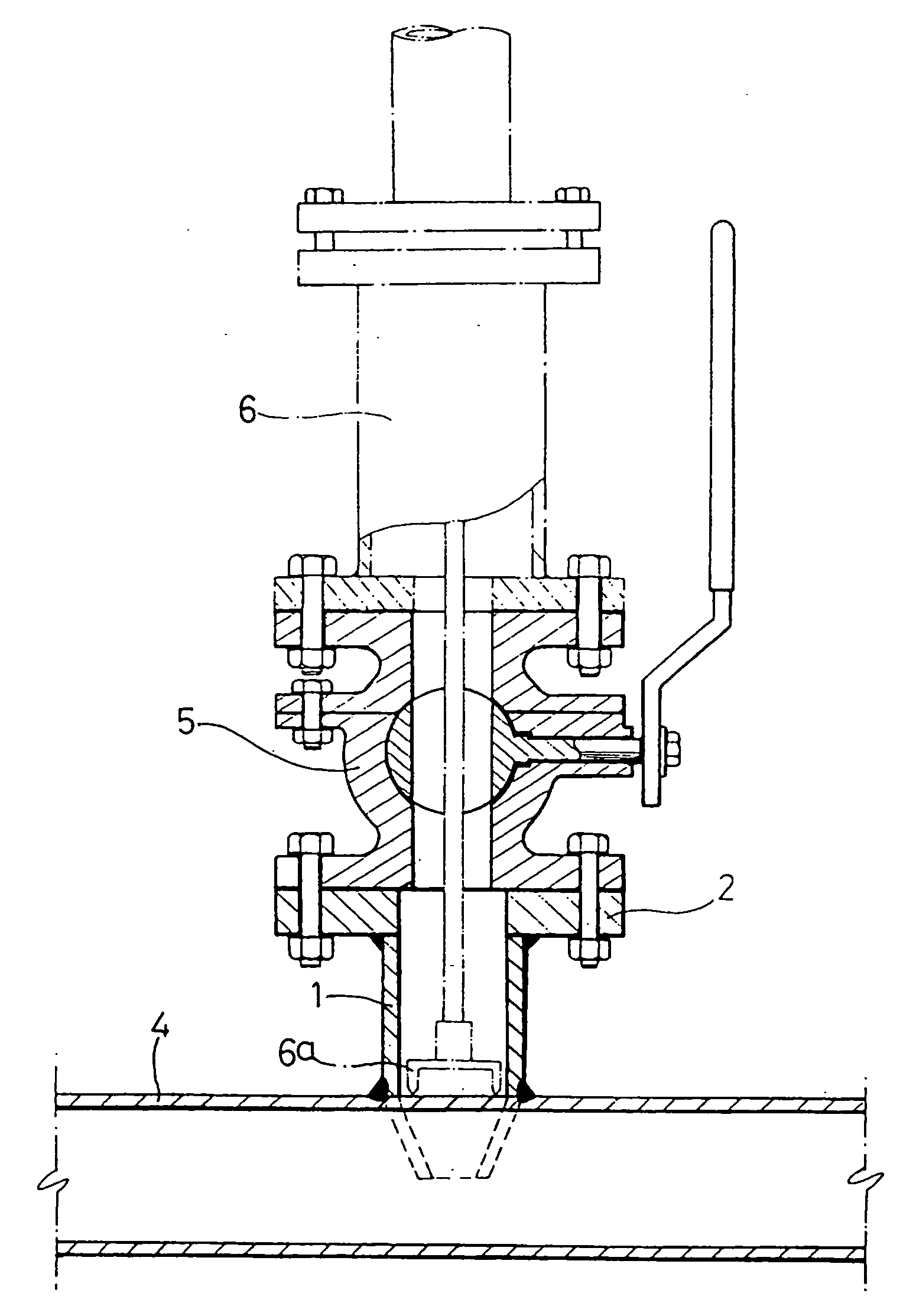
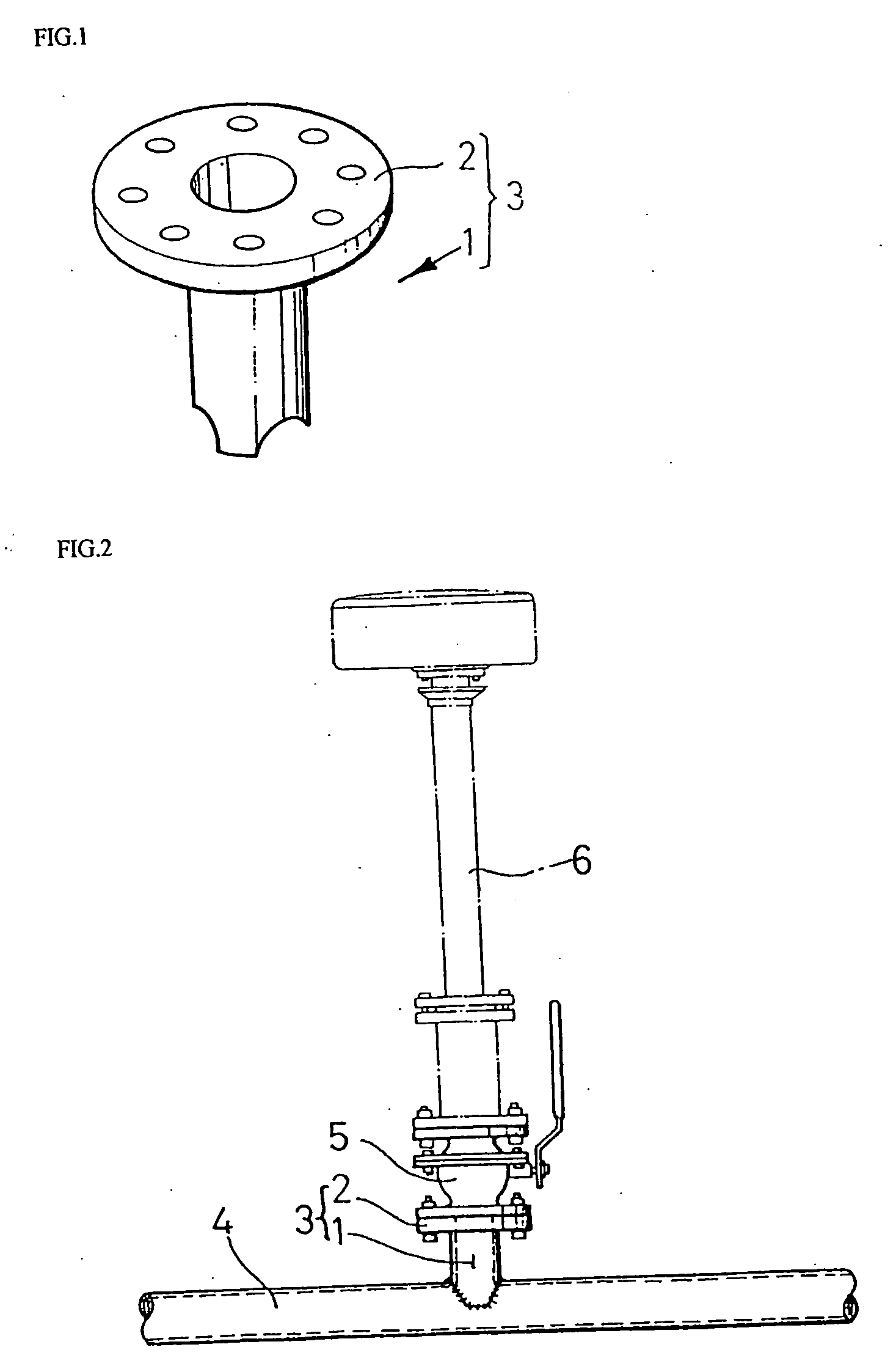
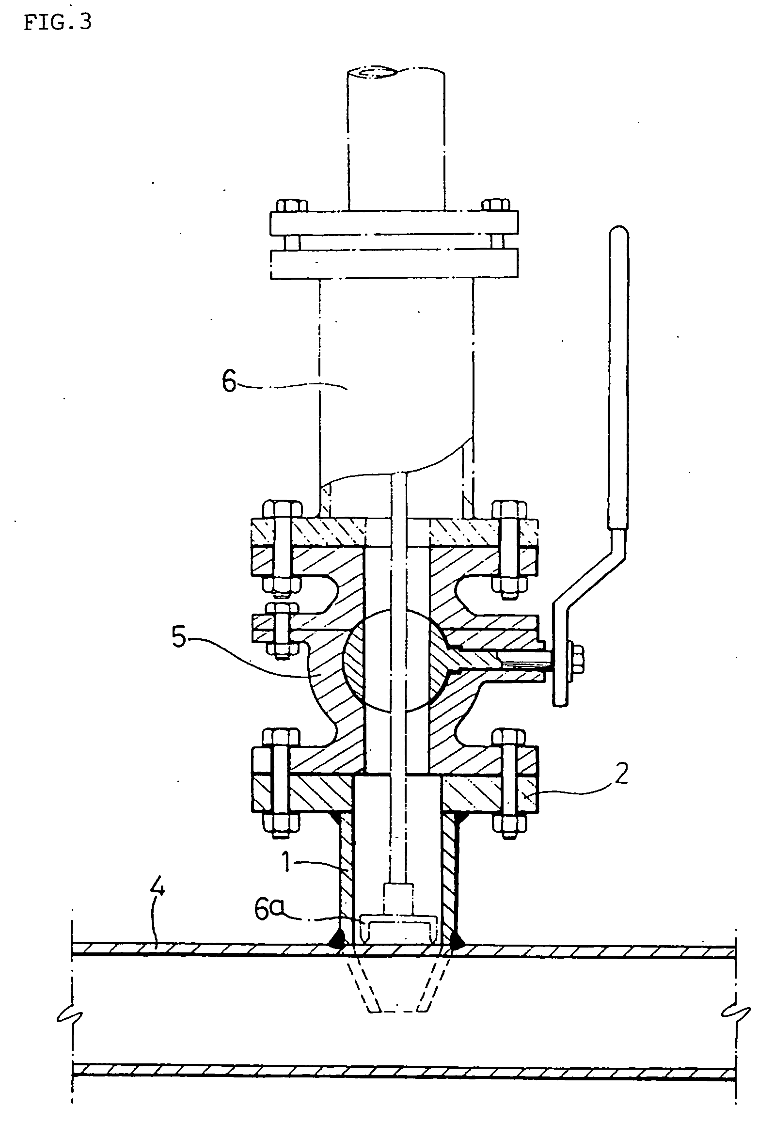
[0057] As shown in the drawings, the pipe interruption fitting of the present invention includes an upper reinforcing plate 31, the circumferential inner surface of which has the same curvature as that of the circumferential outer surface of a pipe, and a vertical pipe...


PUM


Abstract

A pipe interruption fitting having a flange is removable after pipe maintenance work has been completed. The fitting includes an upper reinforcing plate, an inner surface of which has a curvature corresponding to an outer surface of the pipe, and a vertical pipe welded to the upper reinforcing plate. The fitting further includes an adaptor welded to the vertical pipe. Bolt holes are formed in an upper surface of the adaptor. A through hole is formed through the adaptor. An annular groove is formed in an inner surface of the through hole. The flange is removably coupled to the adaptor. Coupling holes are formed in the flange for installation of a boring machine or a stopple machine. The fitting further includes a plug fitted into the through hole of the adaptor and having an expansion plate to be inserted into the annular groove. A cover is adapted to be inserted into the through hole of the adaptor and to be welded thereto.

Description

BACKGROUND OF THE INVENTION [0001] 1. Field of the Invention [0002] The present invention relates generally to pipe interruption fittings which are used for temporarily interrupting fluid, such as gas, water and sewage, chemicals, etc., flowing towards concerned portions of pipes while maintenance work, such as replacement or repair of pipes or connection of branch pipes, is conducted at the concerned portions of the pipes and, more particularly, to a pipe interruption fitting, which has a structure such that, after a pipe has been interrupted and pipe maintenance or repair work has been completed, an unnecessary flange is removed from the fitting, so that the fitting and the periphery can be easily processed for heat insulation and corrosion resistance treatment, and, as well, even if excavation work is conducted adjacent to the pipe interruption fitting, because there is no flange that can be caught by an excavator, the pipe interruption fitting is prevented from being damaged by ...

Claims


Application Information

Patent Timeline
IPC IPC(8): F16L41/00F16L13/02
CPCF16L41/084Y10T137/0447Y10T137/0469Y10T137/612Y10T137/6123F16J15/02F16L41/08F16L55/11
Inventor LEE, WOO KAG
Owner LEE WOO KAG
Why Eureka
Try Eureka