

Manufacture Method of Power Transmission Chain and a Power-Transmission-Chain Manufacturing Apparatus Employed by the Manufacture Method
a manufacturing apparatus and technology of power transmission chain, applied in the direction of manufacturing tools, driving chains, press rams, etc., can solve the problems of pin members that cannot be press-inserted through pin holes, pin members may be out of alignment with pins, and the free play is extremely low, so as to achieve easy and assured assembly, easy to insert into or remove, and reliably position
- Summary
- Abstract
- Description
- Claims
- Application Information
AI Technical Summary
Benefits of technology
Problems solved by technology
Method used
Image

Examples
first embodiment
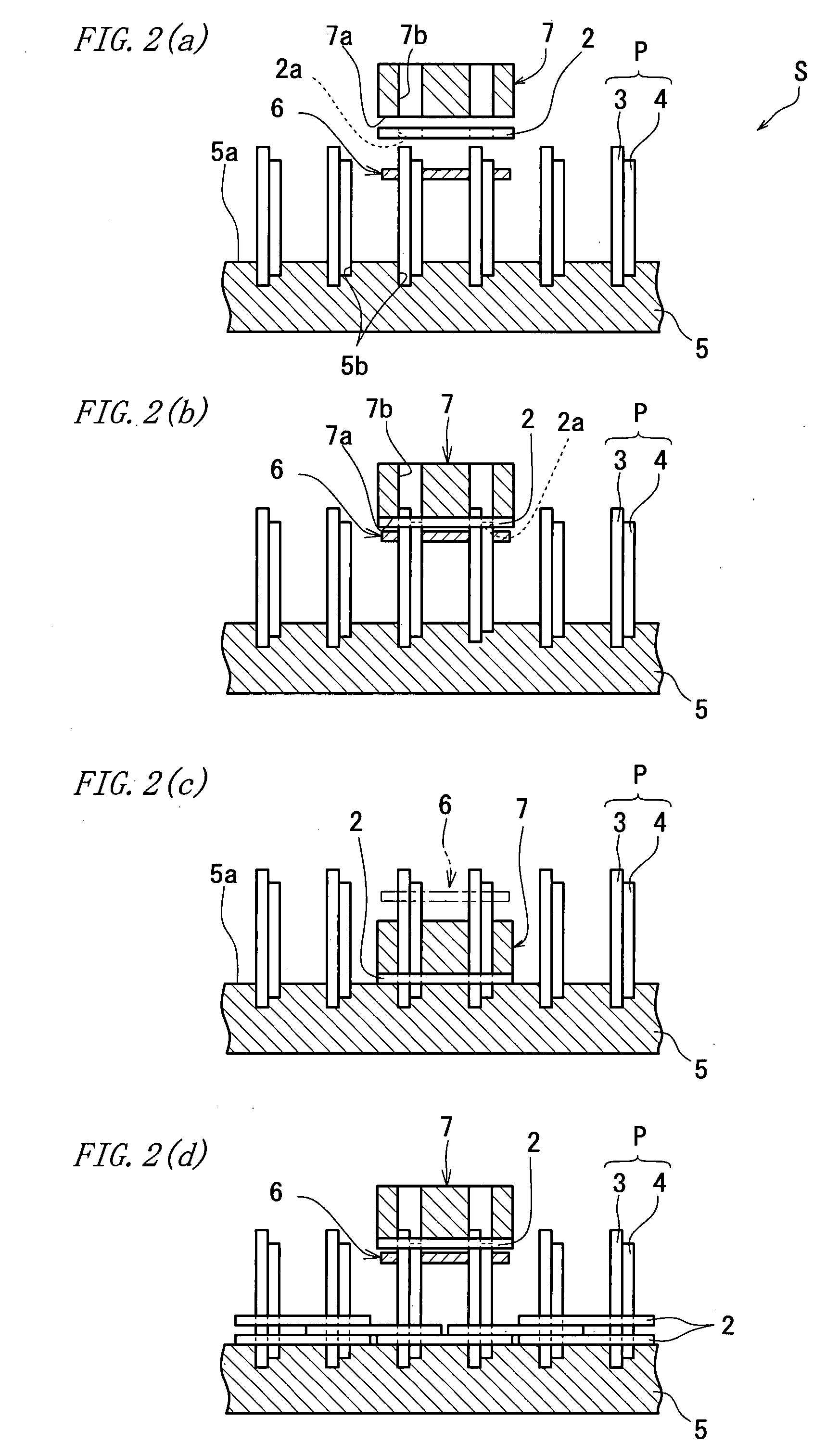
[0085] Next, a detailed description is made on a manufacturing apparatus for the above chain 1 according to the invention. FIG. 2 is a group of schematic diagrams showing the manufacturing apparatus for the chain 1 and a manufacture method of manufacturing the chain 1 by employing the apparatus.
[0086] As shown in FIG. 2(a), the manufacturing apparatus S for the chain 1 includes: an assembling die 5 for retaining plural pins 3 and strips 4 at respective lower ends thereof (as first ends thereof); a retainer jig 6 disposed upwardly of the assembling die 5 for retaining respective upper ends (as second ends) of the pins 3 and strips 4 retained by the assembling die 5; and an upper die 7 disposed upwardly of the assembling die 5 and the retainer jig 6 and moved downward together with the link plate 2 thereby press-inserting the retained pins 3 and strips 4 through the pin holes 2a of the link plate 2.
[0087] The assembling die 5 is a die formed in a rectangular solid shape by using a ca...
second embodiment
[0112] Next, a detailed description is made on a manufacturing apparatus for the above chain 1 according to the invention. FIG. 4 is a group of schematic diagrams showing a manufacturing apparatus for the chain 1 and a manufacture method of the chain 1 employing the apparatus.
[0113] As shown in FIG. 4(a), the manufacturing apparatus S for chain 1 according to the embodiment includes: an assembling die 15 for retaining plural pins 3 and strips 4 at the outside surfaces 3a, 4a thereof; and an upper die 16 disposed upwardly of the assembling die 15 and moved downward together with the link plates 2 thereby press-inserting the retained pins 3 and strips 4 through the pin holes 2a of the link plates 2.
[0114] The assembling die 15 includes: an assembling die body 17 having a rectangular solid shape and formed with a plurality of positioning holes 17a for retaining the outside surfaces 3a, 4a of the pins 3 and strips 4 by receiving the pins and strips; and a stopper 18 including a plurali...
third embodiment
[0156] Next, a detailed description is made on a manufacturing apparatus for the above chain 1 according to the invention. FIG. 7 is a group of schematic diagrams showing an apparatus for manufacturing the chain 1 and a manufacture method of the chain 1 employing the apparatus.
[0157] As shown in FIG. 7(a), the manufacturing apparatus S for the chain 1 includes: a plurality of dummy pins 26 inserted through the pin holes 2a thereby temporarily assembling the link plates 2 in the form of the chain 1; an assembling die 25 for retaining the dummy pins 26; and an upper die 27 disposed upwardly of the assembling die 25 and serving to retain the link plates 2 temporarily assembled.
[0158] The dummy pin 26 is formed in a bar-like shape by using a carbon tool steel, alloy tool steel or the like. The dummy pin 26 is removably retained as inserted through a positioning hole 25a formed in the assembling die 25 in a manner to project vertically from an upper surface 25b of the assembling die 25 ...
PUM
| Property | Measurement | Unit |
|---|---|---|
| Fraction | aaaaa | aaaaa |
| Length | aaaaa | aaaaa |
| Width | aaaaa | aaaaa |
Abstract
Description
Claims
Application Information