Surgical robot and robotic controller

a robotic controller and robotic technology, applied in the field of robotic and computer assisted microsurgery, can solve the problems of affecting the actual surgery, slowing down the actual surgery, and tremor motion creating inaccuracy in surgery, so as to enhance the surgeon's humanly limited senses and accurate harmonization

Active Publication Date: 2007-11-15
MACDONALD DETTWILER & ASSOC INC
View PDF39 Cites 35 Cited by
  • Summary
  • Abstract
  • Description
  • Claims
  • Application Information

AI Technical Summary

Benefits of technology

[0011] The present invention was developed by a neurosurgeon and seeks to utilize the results of primate neurological research which is indicative of a human's actual neurological control structures and logic. Specifically, the proprioceptive and tactile neurophysiology functioning of the surgeon's hands and internal hand control system from the muscular level through the intrafusal fiber system of the neural network is considered in creating the robot and method of operation of the present invention Therefore, the surgery is not slowed down as in the prior art devices, because the surgeon is in better conscious and subsconscious natural agreement and more accurate harmonization with the robotically actuated surgical instruments based on neurological mimicking of the surgeon's behavior through the functioning of the robot. Therefore, the robot can enhance the surgeon's humanly limited senses while not introducing disruptive variables to the surgeon's naturally occurring operation of his neurophysiology. This is therefore also a new field, neurophysiological symbiotic robotics.
[0013] Additionally, the present invention locates the operator interface of the controller robot to work in basically the same orientation and location as in a standard manual operation. In neurosurgery for example, the controller robot may be included in a halo structure fixed to the patient's head in much the same way as a standard retractor system is affixed. Alternatively, the controller robot may be located on a stand, the body, the surgical table or on a rolling or portable platform. In this manner, the surgeon is not immediately forced to operate in an unnatural, detached and isolated environment which is foreign to traditional procedures to which his own body and neurological responses are accustomed.

Problems solved by technology

The common presumption is that tremor motion creates inaccuracies in surgery.
However, in testing, all of these techniques ultimately slow down the actual surgery especially when performed in conjunction with a microscope for viewing the operation.
Another major design issue regards the choice between locating the surgeon in his normal operating position adjacent to the surgical field or locating the surgeon more remotely from the normal operating position at a terminal with a joystick and viewing screen for example.

Method used


Image

  • Surgical robot and robotic controller
  • Surgical robot and robotic controller
  • Surgical robot and robotic controller

Examples


first embodiment

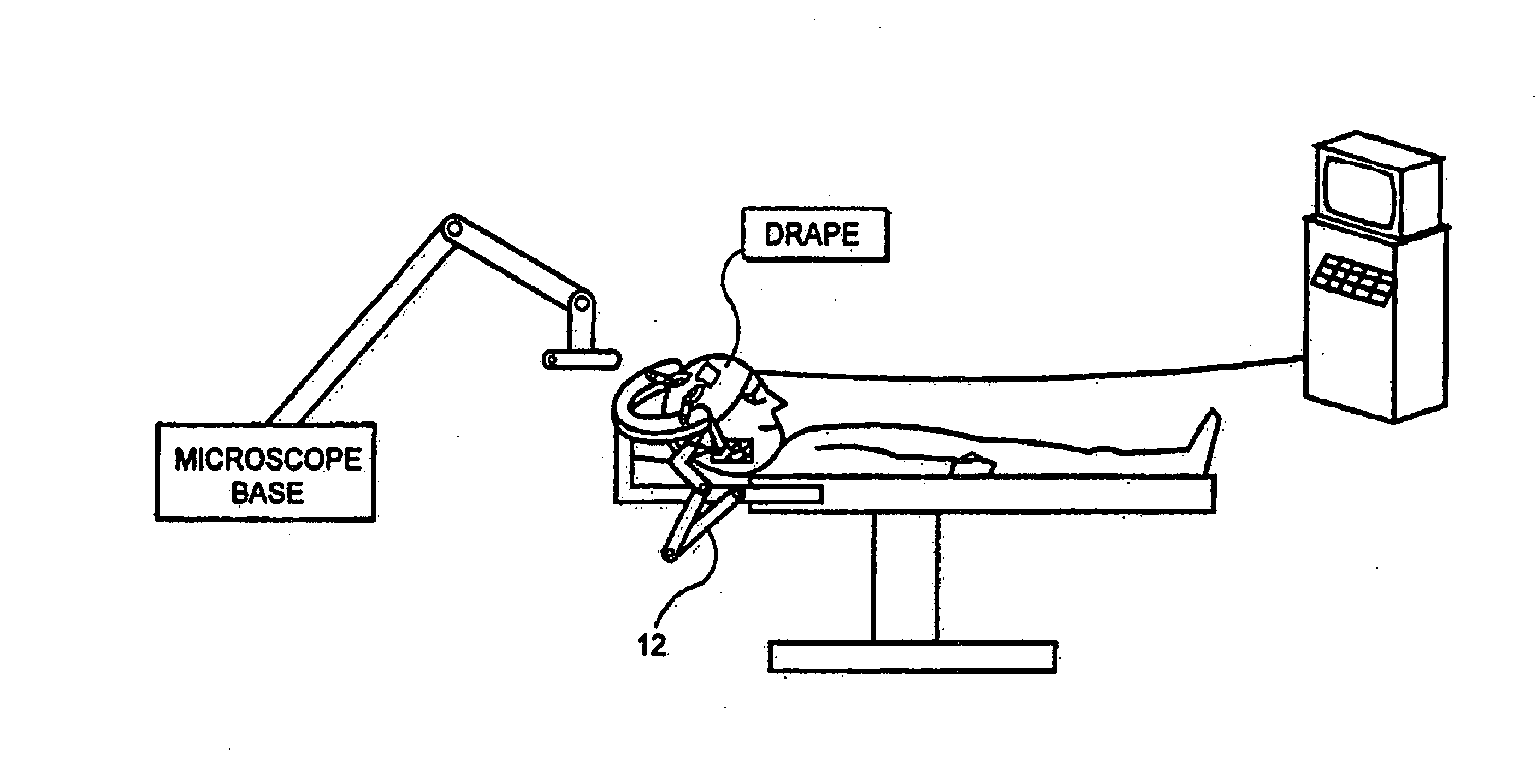
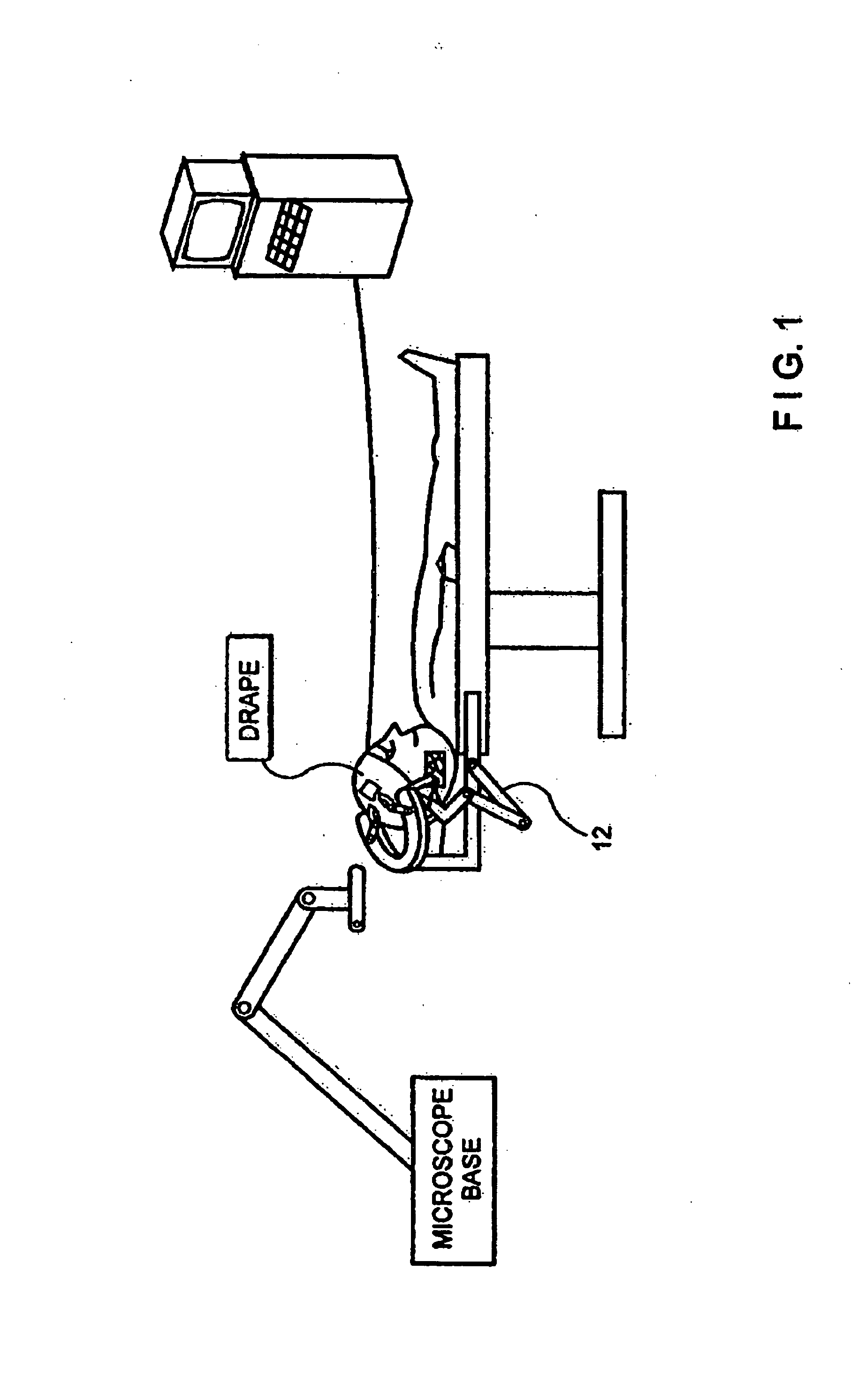
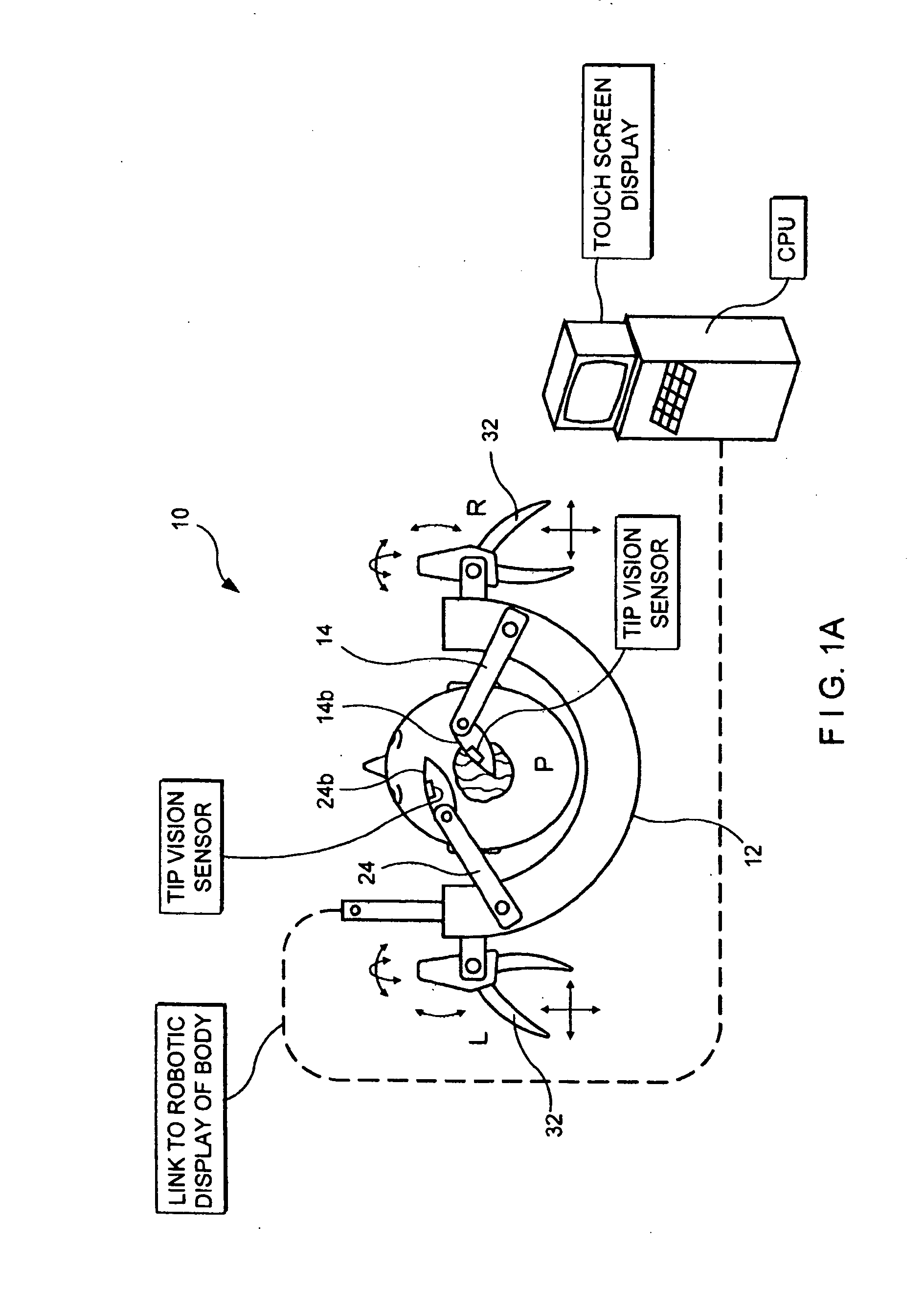
[0053] In light of the above, a first embodiment for a controller robot 10 is discussed below. FIGS. 1a and 1b show the parts of a controller robot 10 located about a head during surgery. A pinned head holder 12 may be attached via cranial screws 16 to a patient P. The pinned head holder 12 may provide a base for mounting a right robotic arm 14 and a left robotic arm 24 via robotic arm mounts 18. Robotic arm mounts 18 are shown as motorized and may provide for controlled motion including motion on the micron scale or smaller, and may be moveable and stabilized in radial tracks 20. The robotic arms may include sub-arms such as those shown in 14a, 14b, 24a, and 24b. Alternatively, the robot arm may be mounted on a portable tray system which would be fixed to the table which is turn fixed to the patient or other combination for fixation. Surgical instruments may be located at the end of the robotic arms as shown and may be interchangeable. An automated instrument changer such as a caro...

second embodiment

[0068] In a second embodiment, the controller robot 10 of the present invention may take the form shown in FIG. 6. The components of the controller robot may include a robotics portion 602, a surgeon workstation portion 604 (not illustrated in FIG. 6), a controller portion 606, and a mobile base 608. The controller portion 606 may be integrated with the robotics portion 602, the workstation portion 604, or the mobile portion 608. The robotics portion 602 may include left and right robotic arms 610, 612 (discussed further below) for carrying out commanded actions. The robotics portion 602 may be adapted to be engaged to an adapter 614 attached to a surgical table 616 (not illustrated in FIG. 6), such that the positioning of the robotics portion 602 relative to the surgical table 616 may be adapted for various types of procedures on varying portions of a patients anatomy simple by adjusting the position of the adapter 614.

[0069] The ability to locate the robotics portion 602 at variou...


PUM


Abstract

The present invention was developed by a neurosurgeon and seeks to mimic the results of primate neurological research which is indicative of a human's actual neurological control structures and logic. Specifically, the motor proprioceptive and tactile neurophysiology functioning of the surgeon's hands and internal hand control system from the muscular level through the intrafusal fiber system of the neural network is considered in creating the robot and method of operation of the present invention. Therefore, the surgery is not slowed down as in the art, because the surgeon is in conscious and subconscious natural agreement and harmonization with the robotically actuated surgical instruments based on neurological mimicking of the surgeon's behavior with the functioning of the robot. Therefore, the robot can enhance the surgeon's humanly limited senses while not introducing disruptive variables to the surgeon's naturally occurring operation of his neurophysiology. This is therefore also a new field, neurophysiological symbiotic robotics.

Description

[0001] The present application is a continuation in part of U.S. patent application Ser. No. 10 / 321,171, filed on Dec. 17, 2002, the contents of which are hereby expressly incorporated by reference thereto into the present application.BACKGROUND [0002] The present invention relates to the field of robotic and computer assisted surgery, and more specifically to equipments and methods for robotic and computer assisted microsurgery. [0003] As shown in U.S. Pat. No. 5,943,914 to Morimoto et al., “Master / slave” robots are known in which a surgeon's hand input is converted to a robotic movement. This is particularly useful for motion scaling wherein a larger motion in millimeters or centimeters by the surgeon's input is scaled into a smaller micron movement. Motion scaling has also been applied in cardiac endoscopy, and neurosurgical target acquisition brain biopsy (with a needle) but only in one degree of freedom, for example only for insertion, not for a full range of natural hand movem...

Claims


Application Information

Patent Timeline
Patent Type & Authority Applications(United States)
IPC IPC(8): A61B19/00B31D1/02
CPCA61B1/05G09B23/28A61B19/203A61B19/22A61B19/2203A61B19/52A61B19/5202A61B19/5212A61B19/5223A61B19/5225A61B19/5244A61B19/56A61B2017/00207A61B2017/0046A61B2017/00464A61B2019/2223A61B2019/223A61B2019/2234A61B2019/2249A61B2019/2269A61B2019/2276A61B2019/2288A61B2019/2292A61B2019/2296A61B2019/461A61B2019/464A61B2019/465A61B2019/5229A61B19/20A61B90/10A61B2034/742A61B34/75A61B90/36A61B34/20A61B2090/064A61B34/70A61B90/30A61B34/25A61B90/361A61B34/30A61B90/14A61B34/37A61B34/35A61B2034/305A61B34/72A61B34/74A61B34/76A61B34/77A61B2090/061A61B2090/065A61B90/20A61B90/37A61B2090/372
Inventor LIPOW, KENNETH L.GREGORIS, DENNIS
Owner MACDONALD DETTWILER & ASSOC INC
Why Eureka
Try Eureka