Atomizer
a technology of atomizer and atomizer body, which is applied in the field of atomizer, can solve the problems of not being able to be easily operated, and achieve the effects of compact structure, low overall height, and simple and inexpensive construction
- Summary
- Abstract
- Description
- Claims
- Application Information
AI Technical Summary
Benefits of technology
Problems solved by technology
Method used
Image
Examples
first embodiment
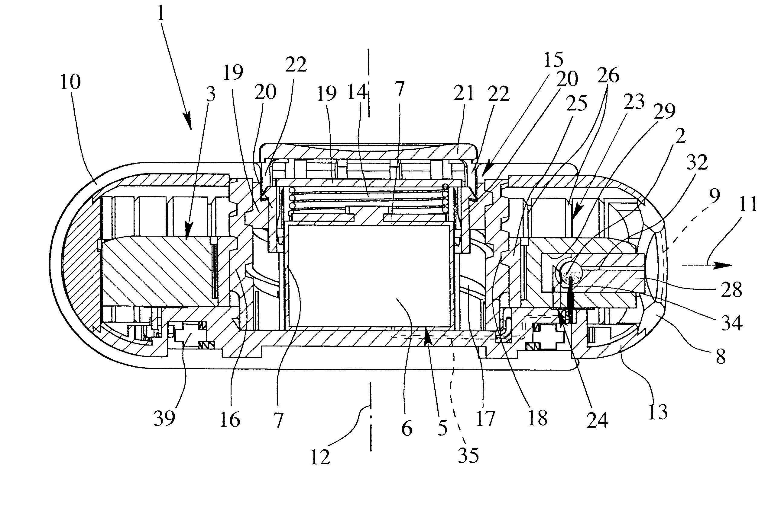
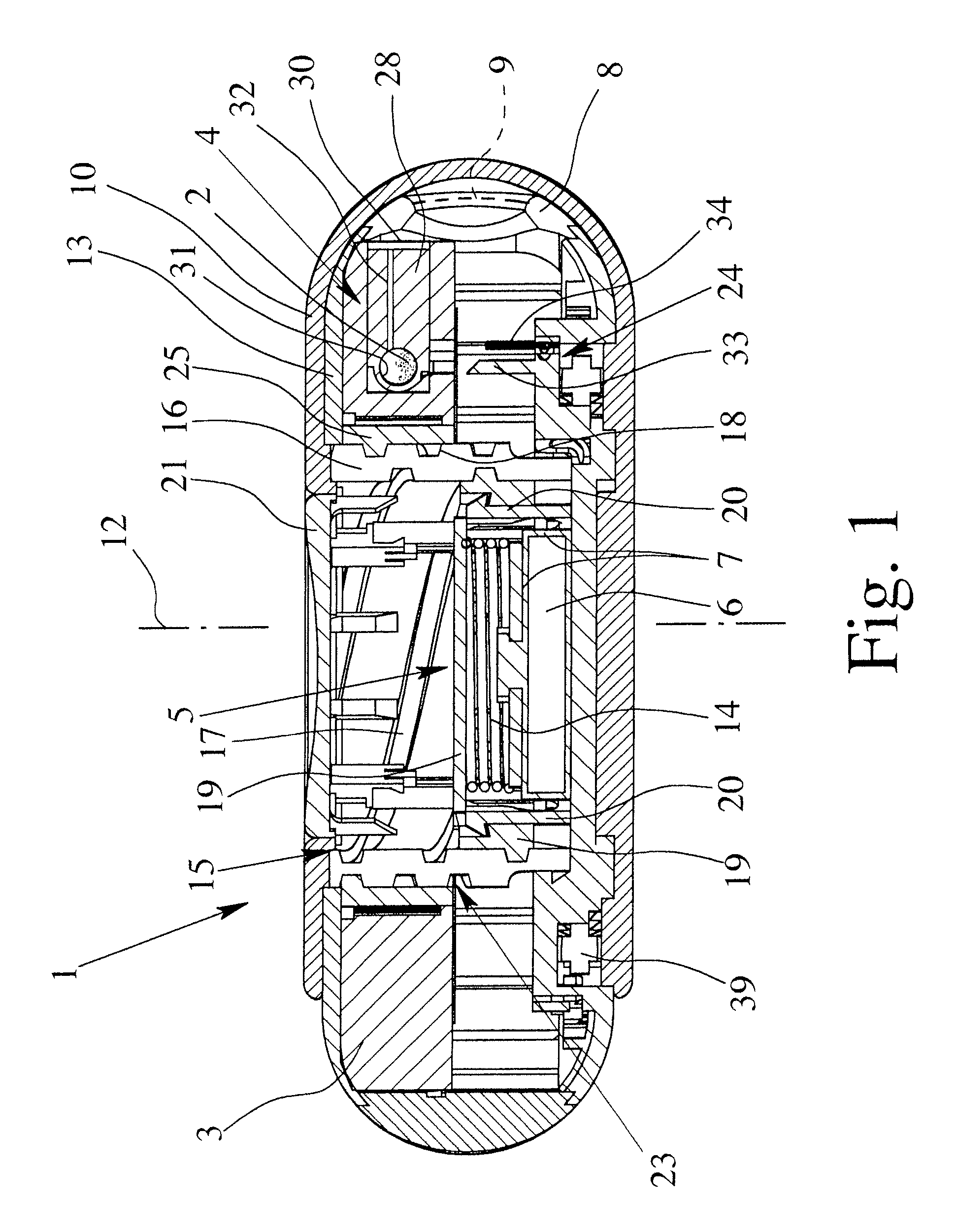
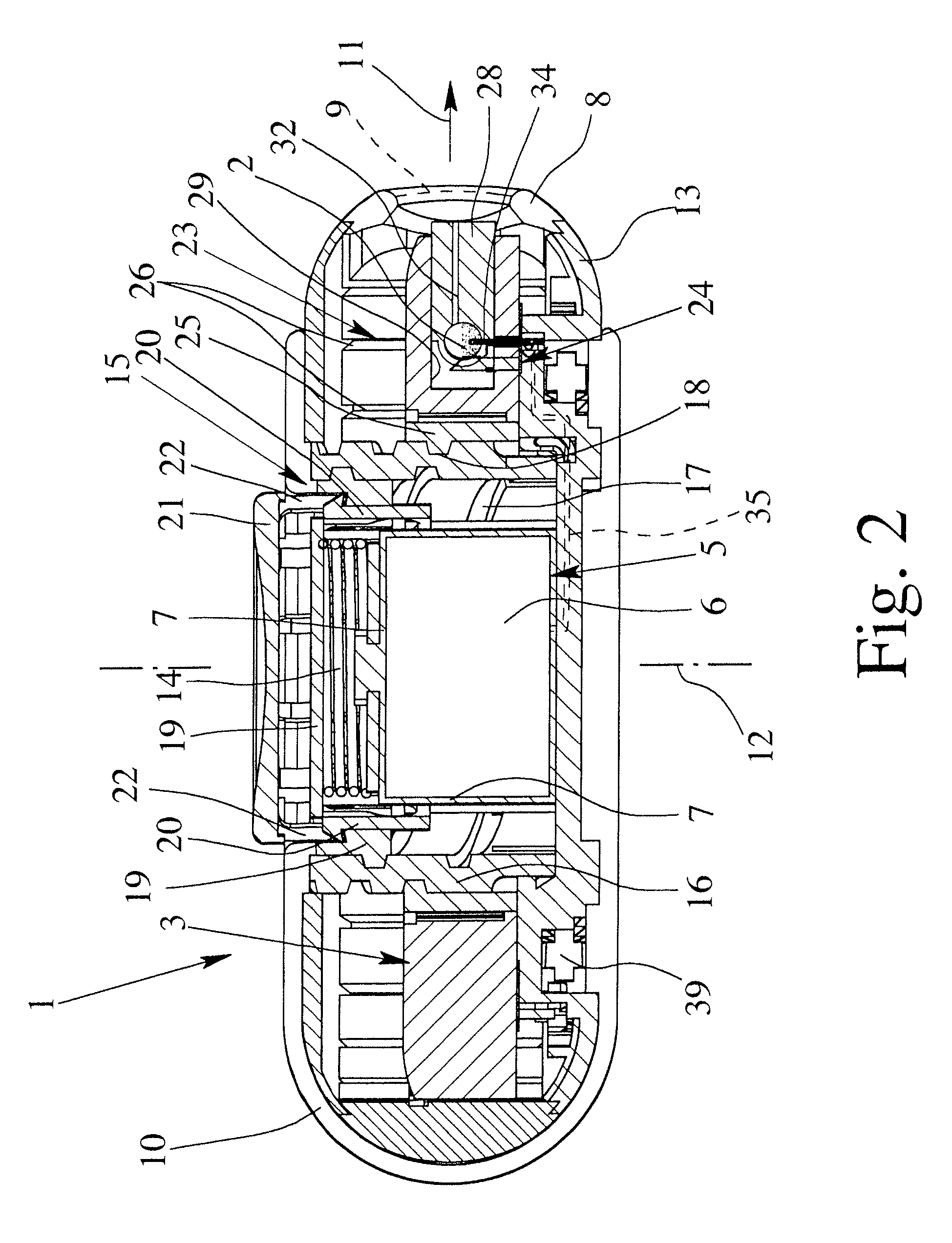
[0054]FIG. 1 shows in schematic section a proposed atomizer 1 in the transportation position. In particular, it is a preferably portable inhaler, particularly preferably, for aerosol therapy.
[0055] The atomizer 1 is designed to deliver and atomize a formulation 2, preferably powder. In particular, the atomizer 1 can be used for a formulation 2 in the sense explained above.
[0056] The formulation 2 is preferably pre-metered into individual doses which can be delivered one after another by the atomizer 1, particularly for inhalation.
[0057] The atomizer 1 has a reservoir 3 or is designed to hold one. If necessary, the reservoir 3 can be inserted in the atomizer 1, and optionally, replaced for repeated use of the atomizer 1.
[0058] The reservoir 3 has a plurality of receptacles 4, each containing one dose of the formulation 2. The receptacles 4 may be, e.g., blister pockets, but preferably, contain inserts 28 with the respective dose of the formulation 2. The reservoir 3 is preferably...
second embodiment
[0147]FIGS. 6 & 7 show schematic views of the proposed atomizer 1. FIG. 6 shows the atomizer 1 in the closed position with the receptacle 4 not yet pierced. FIG. 7 shows the atomizer 1 in the activated state with the receptacle 4 opened or pierced.
[0148] In the second embodiment, the reservoir 3 is not axially movable, in contrast to the first embodiment. Instead, the connecting device 24 is preferably axially slidable or movable. In the embodiment shown, the reservoir 3 is held by a rotatable inner part 41. The connecting device 24 (at least the connecting element 34 thereof and preferably the fingers 33 thereof) is mounted on a carrier 42, which is axially movable but not rotatable. The carrier 42 is, in turn, preferably axially movable by opening and / or closing the cover 10, particularly by means of the gear 15 which is not shown in detail here.
[0149] The carrier 42 preferably has axially operating teeth 43, e.g., with sawtooth-shaped sliding surfaces or the like, which cooperat...
fourth embodiment
[0153]FIG. 9 shows in schematic view the proposed atomizer 1 in the transportation position or locked state. Here, the cover 10 is in the form of a cap. The pivot axis of the cover 10 is eccentrically arranged or formed, particularly in the region of the periphery or edge of the atomizer 1. In contrast to the previous embodiments, the cover 10 essentially only covers the mouthpiece 8.
[0154] In the fourth embodiment, the opening and / or closing of the cover 10 is preferably not coupled with the other functions of the atomizer 1.
[0155] The atomizer 1 has a release mechanism 46 which is constructed, in particular, as a peripherally movable slide.
[0156]FIG. 10 is a schematic sectional view the atomizer 1 in the unlocked state.
[0157] In the fourth embodiment, the atomizer 1 has two preferably external housing parts, particularly an upper housing part 47 and a lower housing part 48, which are movable axially towards one another. In particular, the housing parts 47, 48 are biased away fr...
PUM
 Abstract
Description
Claims
Application Information
 - R&D
- Intellectual Property
- Life Sciences
- Materials
- Tech Scout
- Unparalleled Data Quality
- Higher Quality Content
- 60% Fewer Hallucinations
Browse by: Latest US Patents, China's latest patents, Technical Efficacy Thesaurus, Application Domain, Technology Topic, Popular Technical Reports.
© 2025 PatSnap. All rights reserved.Legal|Privacy policy|Modern Slavery Act Transparency Statement|Sitemap|About US| Contact US: help@patsnap.com


