Method and Apparatus for Transnasal Ventilation

a technology of transnasal ventilation and method, which is applied in the field of respiratory monitoring, can solve problems such as errors in the setup of equipment or equipment, and achieve the effects of reducing intrusion, reducing safety and control, and reducing the risk of infection

Inactive Publication Date: 2007-11-22
POG
View PDF0 Cites 13 Cited by
  • Summary
  • Abstract
  • Description
  • Claims
  • Application Information

AI Technical Summary

Benefits of technology

[0013] The design of the exemplary embodiments minimize the risk that the apparatus will become dislodged during surgery. In addition, the exemplary embodiments increase safety and control during medical procedures because they maintain oxygen delivery in a more “constant flow” state by supplying constant, passively delivered oxygen to a patient's pharynx. The constant oxygen delivery allows for deeper, more controlled sedation (anesthesia) of the patient. In addition, the exemplary embodiments minimize intrusion on the surgical field of the face.

Problems solved by technology

Further, when supplying oxygen to or collecting exhale gases from a patient, errors can occur in the setup of the equipment or apparatus.

Method used


Image

  • Method and Apparatus for Transnasal Ventilation
  • Method and Apparatus for Transnasal Ventilation
  • Method and Apparatus for Transnasal Ventilation

Examples


example 1

1. Overview of Exemplary Embodiments

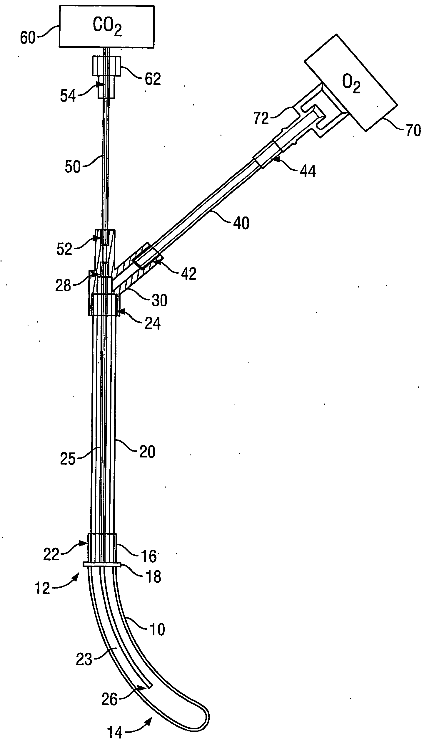
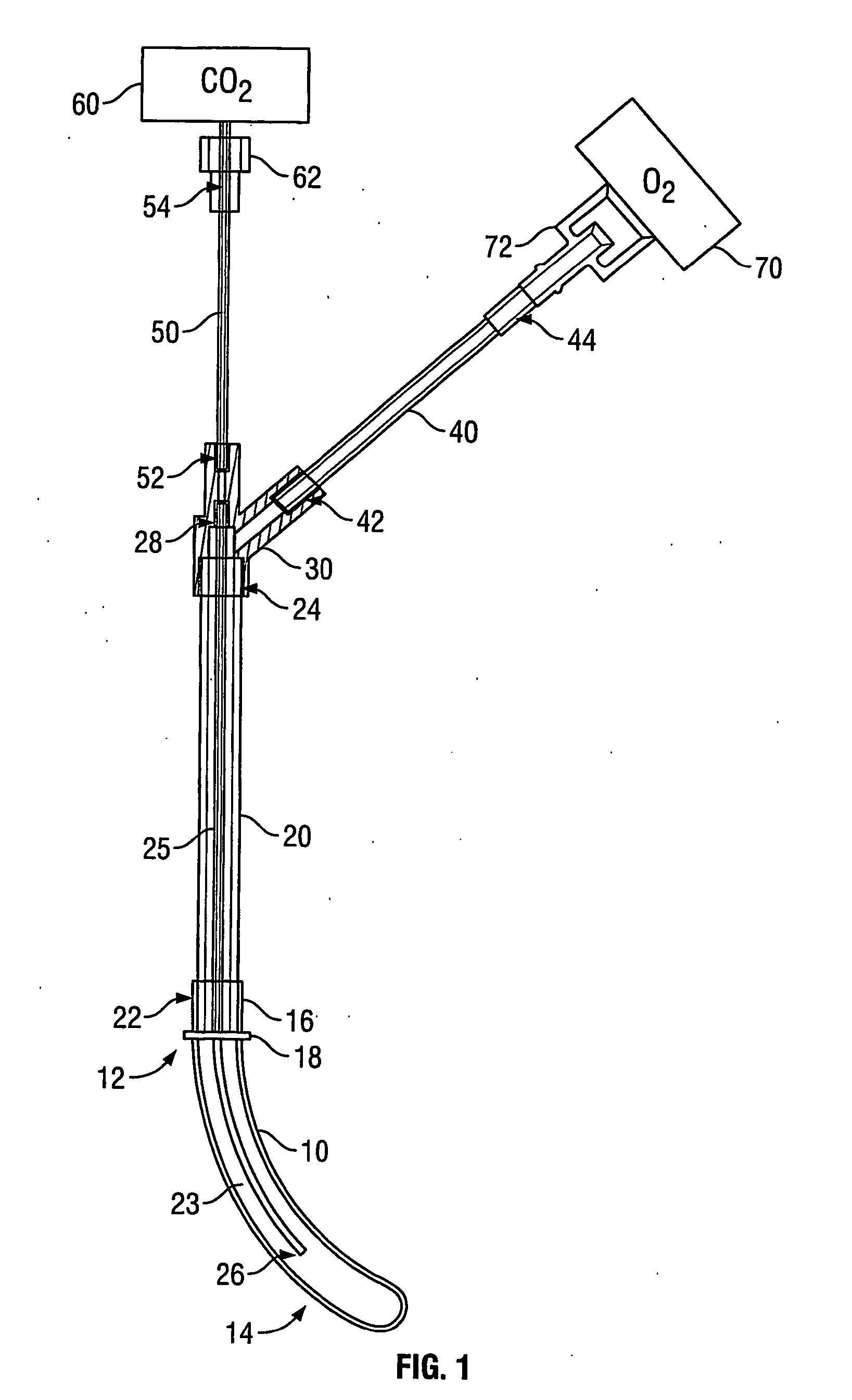
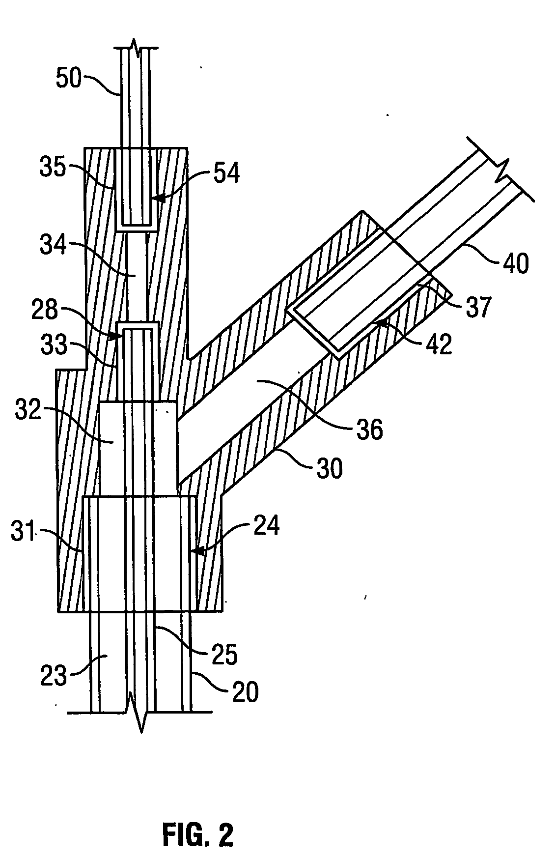
[0032] Referring to FIG. 1, in accordance with an exemplary embodiment, a transnasal ventilation apparatus might comprise an insertion guide 10, a first tube 20, a inner tube 25, a junction 30, a second tube 40, and a third tube 50. The first tube 20 might comprise a first end 24 and a second end 22. The inner tube 25 might comprise a first end 26 and a second end 28. The second tube 40 might comprise a first end 42 and a second end 44. And the third tube 50 might comprise a first end 52 and a second end 54. Further, the insertion guide 10, the first tube 20, the inner tube 25, the junction 30, the second tube 40, and the third tube 50 might comprise a single apparatus by, for example, being fused or otherwise bonded together or integral. Other embodiments are possible as well.

[0033] Referring to FIG. 1, the insertion guide 10 might comprise a proximal end 12 and a distal end 14. Although it need not be, insertion guide 10 might be tapered. For ...

example 2

1. Overview of Exemplary Embodiments

[0048] Referring to FIG. 3, in accordance with an exemplary embodiment, a transnasal ventilation apparatus might comprise an insertion guide 10, a first tube 20, a junction 30, a second tube 40, and a third tube 50. Referring to FIG. 4, in accordance with another exemplary embodiment, a transnasal ventilation apparatus might comprise an insertion guide 10, a first tube 20 fixedly attached to the insertion guide 10, a junction 30, a second tube 40, and a third tube 50, the junction 30 being integral with the first, second, and third tubes. FIG. 5 shows an exemplary embodiment similar to the exemplary embodiment of FIG. 4, but with the junction 30 being fused to the first, second, and third tubes. Although not shown, other embodiments are also possible. For instance, in another embodiment, the insertion guide 10 might be fixedly attached to the first tube 20, but the junction 30 might not be integral with or fused to any or all of the first, second...

example 3

1. Overview of Exemplary Embodiments

[0059] Referring to FIGS. 6 and 7, in accordance with another embodiment, a transnasal ventilation apparatus might comprise an airway, such as an insertion guide 10, a flow-through airway fitting 80, a first tube 20, a second tube 25, a third tube 40, and a fourth tube 50. The first tube 20 might comprise a first end 24 and a second end 22. The second tube 25 might comprise a first end 26 and a second end 28. The third tube 40 might comprise a first end 42 and a second end 44. And the fourth tube 50 might comprise a first end 52 and a second end 54. Although shown as separate components, the insertion guide 10, the flow-through airway fitting 80, the first tube 20, the second tube 25, the third tube 40, and the fourth tube 50 might comprise a single apparatus by, for example, being fused or otherwise bonded together or integral. Other embodiments are possible as well.

[0060] As shown in FIG. 6, the first tube 20 and the second tube 25 can be coup...


PUM


Abstract

An apparatus and method for delivering oxygen to a nasopharynx and withdrawing exhale gas from the nasopharynx to a carbon dioxide monitor. In one embodiment, the apparatus can comprise one or more tubes and an airway fitting forming an airway. The airway fitting can be configured to engage at least one of the tubes and maintain the one or more tubes within the airway, and to provide an outlet to the atmosphere for the airway. In another embodiment, the tube might be in fluid communication with a junction that can direct oxygen from an oxygen supply through the tube and exhale gas from the tube to the carbon dioxide monitor. Further, the tube might comprise an outer tube and an inner tube.

Description

[0001] This application is a continuation-in-part of U.S. patent application Ser. No. 10 / 441,557, filed on May 20, 2003.BACKGROUND [0002] 1. Field of the Invention [0003] The present invention relates to the field of respiratory monitoring of carbon dioxide levels and the supplying of oxygen to a patient. [0004] 2. Description of the Related Art [0005] It is often desirable or necessary to exchange gas with a subject, such as a medical patient. Using the example of a medical patient, oxygen can be supplied to the patient, and exhale gases such as carbon dioxide can be collected from the patient. When supplying oxygen to the patient, it may be efficient to transfer oxygen to the patient in a stable and controlled location. Likewise, carbon dioxide levels might be monitored more accurately if based on readings taken at a stable and controlled location. Further, when supplying oxygen to or collecting exhale gases from a patient, errors can occur in the setup of the equipment or apparat...

Claims


Application Information

Patent Timeline
Patent Type & Authority Applications(United States)
IPC IPC(8): A61M15/08A61M16/04
CPCA61M2016/0413A61M16/0461A61M2230/432A61M16/0833A61M16/042A61M16/085
Inventor LYONS, JAMES R.RUSSEL, ROBERT G.
Owner POG
Why Eureka
Try Eureka