Used paper recycling apparatus and its constitutent devices

a technology of used paper and constitutent devices, which is applied in paper recycling, textiles and papermaking, paper recycling, etc., can solve the problems of large manual labor needed for collecting used paper, inconvenient use, and incineration, so as to prevent the leakage of confidential information and private information, the effect of being friendly to the environment and low running cos

Inactive Publication Date: 2007-11-22
VIEWDLE INC
View PDF8 Cites 13 Cited by
  • Summary
  • Abstract
  • Description
  • Claims
  • Application Information

AI Technical Summary

Benefits of technology

[0147](6) Moreover, the apparatus structure is compact, and it can be installed not only in large office, but also in small shop or general household, and from this point of view, too, leak of confidential information and private information can be securely prevented.
[0148](7) The water used in the pulp making section is the water collected from the paper making unit after dewatering in water circulation system, and the driving source of the pulp making section and paper making section is the driving power source driven by an alternating-current power source for general household, and it is friendly to the environment, low in running cost, and economical.
[0149](8

Problems solved by technology

For recycling of used paper, a tremendous manual labor is needed for collecting used paper, and used paper collection involves various problems, such as mixing of foreign matter by garbage collectors, defective classification due to lack of knowledge about used paper recycling, and entry of harmful objects, and if used paper is collected, in order to recycle by 100 percent, final checking by specialists and cleaning works are needed.
On the other han

Method used


Image

  • Used paper recycling apparatus and its constitutent devices
  • Used paper recycling apparatus and its constitutent devices
  • Used paper recycling apparatus and its constitutent devices

Examples


embodiment 1

Preferred Embodiment 1

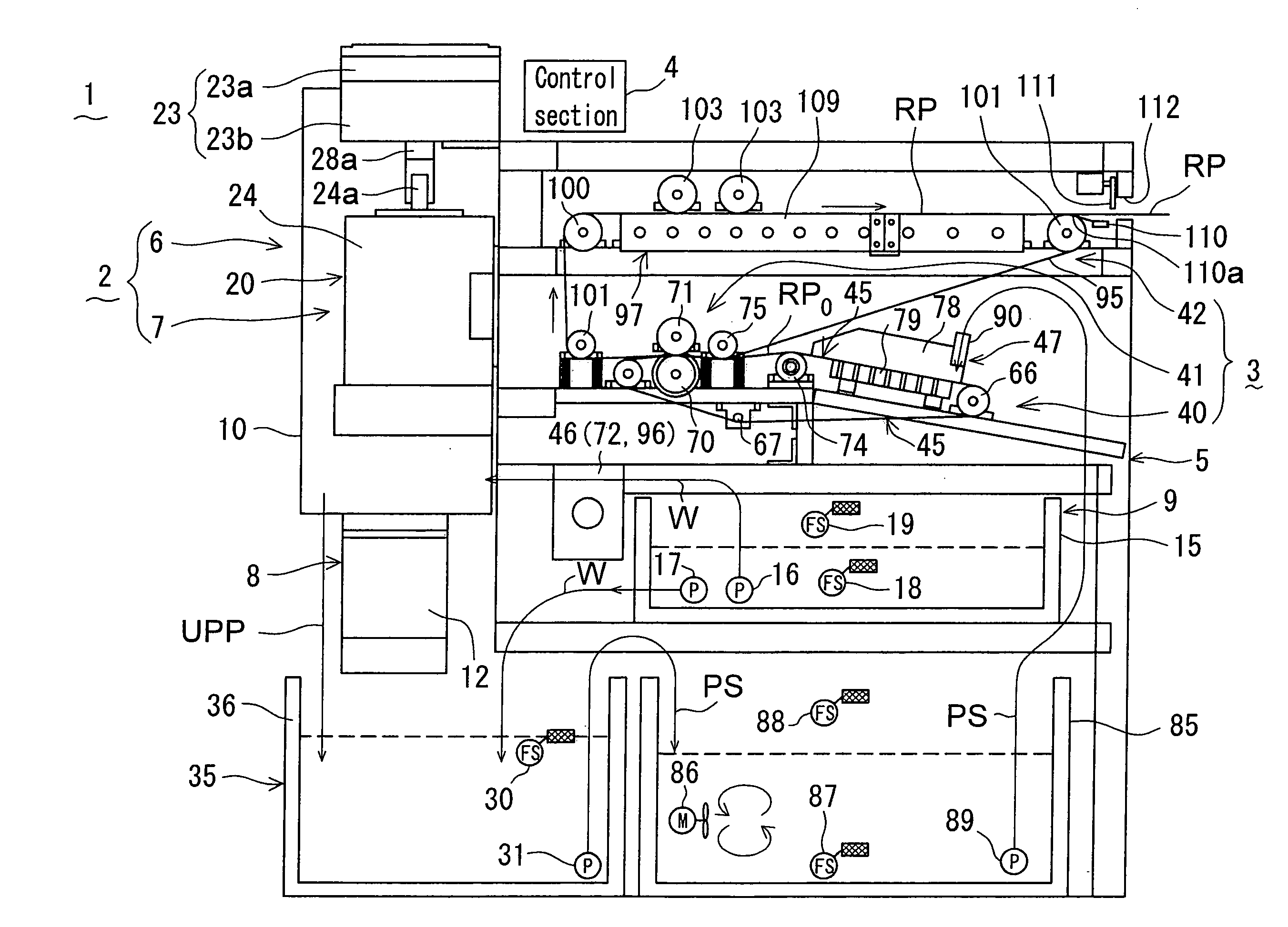
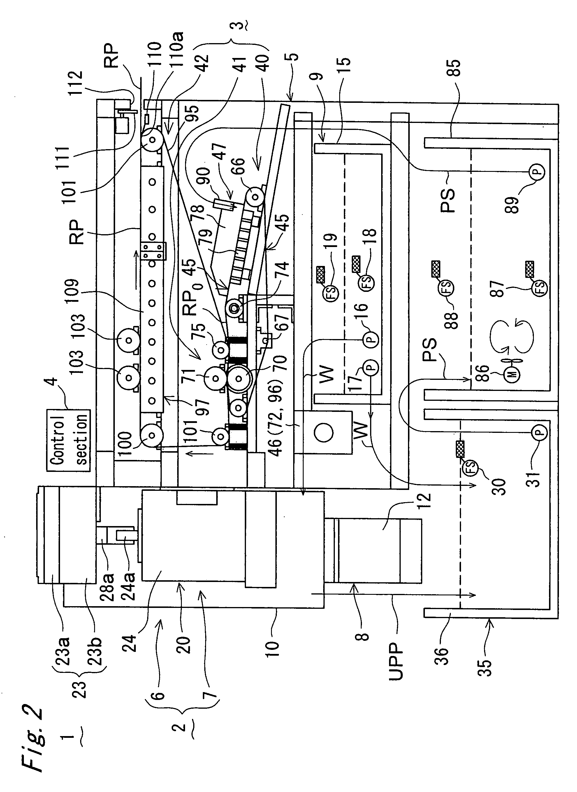
[0193]A used paper recycling apparatus of the invention is shown in FIG. 1 to FIG. 10 (FIG. 10A, FIG. 10B), and this used paper recycling apparatus 1 is specifically installed at the site of origin of used paper, and it is an apparatus for manufacturing recycled paper at the site without disposing or discarding the used paper UP, and such used paper UP includes confidential documents occurring in government offices and private companies, and private letters in general household, and other used and unnecessary documents.

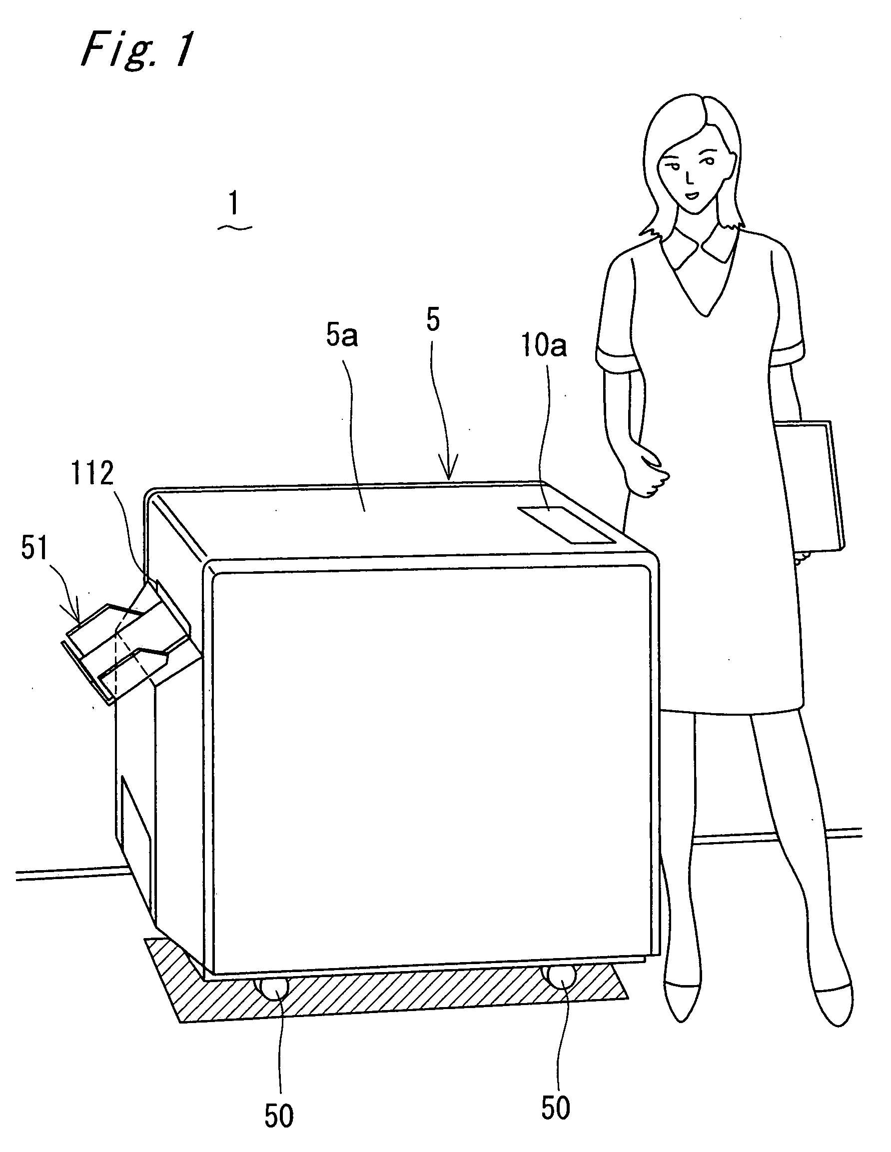
[0194]The used paper recycling apparatus 1 has a furniture size as shown in FIG. 1, that is, size and shape similar to office equipment, such as document rack, locker, desk, copier, or personal computer, and is mainly composed of a pulp making section 2, a paper making section 3, and a control section 4 as shown in FIG. 2, and these sections 2 to 4 are contained in an apparatus case 5 in a compact design, and a drive source of the pulp making sec...

embodiment 2

Preferred Embodiment 2

[0331]This preferred embodiment is shown in FIG. 11 to FIG. 14 (FIG. 14A, FIG. 14B), and is similar to preferred embodiment 1, except that the structure of mashing unit 7 is modified.

[0332]The mashing unit 7 of the preferred embodiment has one mashing machine 120 same as in preferred embodiment 1.

[0333]As shown in FIG. 11, the mashing machine 120 is mainly composed of a plurality (two in this example) of relatively moving mashing members 121, 122 disposed oppositely across a tiny mashing clearance A.

[0334]The two mashing members 121, 122 are relatively rotating disks, and the upper side mashing member 121 is fixed, and the lower side mashing member 122 is rotating.

[0335]That is, same as in preferred embodiment 1, the upper fixed mashing member 121 is fixed to the inner side of the ceiling of the upper tank 23a by proper fixing means, and the lower rotating mashing member 122 is concentrically and rotatably disposed oppositely to the fixed mashing member 121 acr...

embodiment 3

Preferred Embodiment 3

[0342]This preferred embodiment is shown in FIG. 15 and FIG. 16, and is similar to preferred embodiment 1, except that the structure of mashing unit 7 is modified.

[0343]The mashing unit 7 of the preferred embodiment has one mashing machine 130 same as in preferred embodiment 1. As shown in FIG. 15, the mashing machine 130 is mainly composed of a plurality (two in this example) of relatively moving mashing members 131, 132 disposed oppositely across a tiny mashing clearance A.

[0344]The two mashing members 131, 132 are relatively rotating bowls, and the outline shape is as shown in FIG. 16.

[0345]A mashing tank 133 containing these mashing members 131, 132 in closed state has a contour section along the outer circumference of the both mashing members 131, 132 as shown in FIG. 15, and same as in preferred embodiment 1, it has an upper and lower divided structure having upper tank 133a and lower tank 133b engaged with each other.

[0346]Specifically, the upper mashing...


PUM

PropertyMeasurementUnit
Temperatureaaaaaaaaaa
Timeaaaaaaaaaa
Flow rateaaaaaaaaaa

Abstract

A used paper recycling apparatus being installed in a room of a small shop or the like, friendly to the environment, low in running cost, and capable of maintaining a high confidentiality. The apparatus includes, in an apparatus case of furniture size, a pulp making section for manufacturing used paper pulp by macerating and mashing used paper, a paper making section for manufacturing recycled paper by making the used paper pulp manufactured in the pulp making section, and a control section for driving and controlling the pulp making section and paper making section, in which the pulp making section comprises a macerating unit for macerating the used paper by agitating and tearing, and a mashing unit for mashing the used paper macerated in the macerating unit, and the mashing machine of the mashing unit has mashing members rotating relatively being disposed oppositely across a slight mashing clearance, and the opposing faces of these mashing members cooperate to form a mashing action surface, and the used paper passing the mashing clearance is pressurized and mashed by the mashing action surface, and the inks forming characters and patterns on the used paper are pulverized.

Description

BACKGROUND OF THE INVENTION[0001]1. Field of the Invention[0002]The invention relates to a used paper recycling apparatus and its constituent devices, and more particularly to a used paper recycling technology for regenerating into recycled paper, at the site of origin of used paper, without discarding the used paper.[0003]2. Description of the Related Art[0004]Used paper of various types occurs not only in government offices or private companies, but also in daily life or general household. Used paper is usually discarded, incinerated, or disposed as refuse.[0005]On the other hand, in the global concern about effective use of limited resources on earth, various technologies have been developed to regenerate and reuse the used paper being disposed and discarded so far.[0006]Such used paper recycling technologies are mostly installed in paper making industry, and the water paper recycling plant requires, like the ordinary paper making plant, a vast land, an immense investment, and a ...

Claims


Application Information

Patent Timeline
IPC IPC(8): D21B1/32
CPCD21B1/32D21C5/02D21H11/14D21F9/00D21C9/18Y02W30/64D21B1/08D21H17/01
Inventor TAMAI, SHIGERUKOYAMA, YUJI
Owner VIEWDLE INC
Why Eureka
Try Eureka