
Glitter glue tube dispensing apparatus

a technology of glitter glue and dispensing apparatus, which is applied in the direction of instruments, pliable tubular containers, volume meters, etc., can solve the problems of difficult to reliably control the amount of glitter glue being dispensed from the tube, user is often unable to dispense most of the glitter glue tube from the tube, and not all of the glitter glue tube, etc., to achieve convenient control and improve the dispensing of glitter glue.

Inactive Publication Date: 2007-11-22
PNC BANK NAT ASSOC
View PDF13 Cites 13 Cited by
  • Summary
  • Abstract
  • Description
  • Claims
  • Application Information

AI Technical Summary

Benefits of technology

[0005]It is another object of the present invention to provide a new and improved dispensing apparatus receivable of a tube of glitter glue and which dispenses the glitter glue from the tube in an easily controllable manner.
[0007]It is still another object of the present invention to provide a new and improved dispensing apparatus for automatically dispensing glitter glue from a tube without requiring manual effort to squeeze the tube.
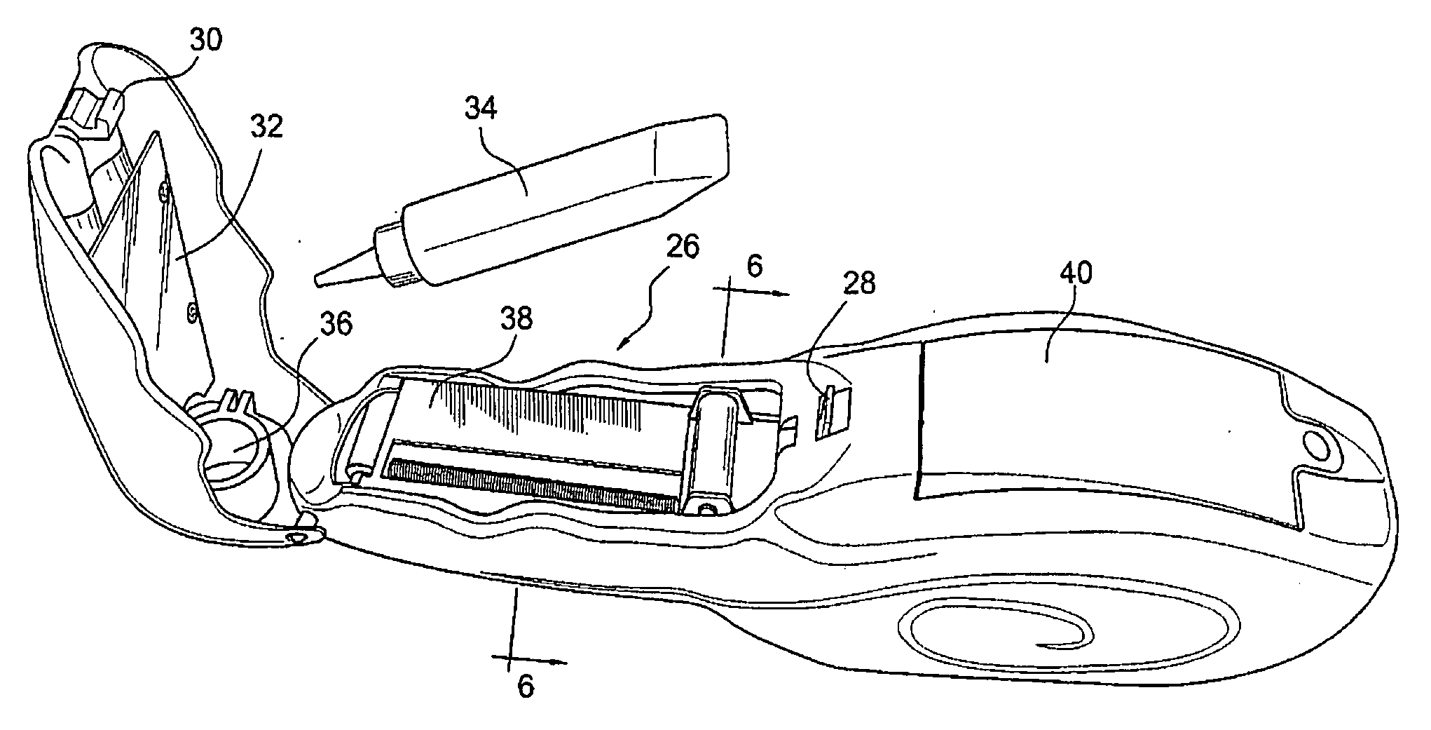
[0008]In order to achieve these objects and others, a dispensing apparatus in accordance with the invention for dispensing glue from a tube, such as a glitter glue tube, includes an elongate, hand-held housing, a cover member movably connected to a front part of the housing and defining a tube-receiving compartment with the housing which is opened upon movement of the cover member relative to the housing, an actuatable trigger arranged on the housing, and a compression mechanism arranged in the housing for engaging the tube when in the compartment and compressing the tube upon actuation of the trigger in order to cause glitter glue from the tube to be pushed out of a dispensing opening at a front end of the tube. Actuation of the trigger by the user therefore provides for a controlled dispensing of glue from the tube. Moreover, the compression mechanism engages a rear end of the tube and moves gradually toward the front end of the tube to thereby improve the dispensing of the glitter glue from the tube in that most of the glitter glue in the tube can be dispensed, and certainly significantly more than if the tube were to be manually compressed.
[0010]The compression mechanism is preferably designed to cause rotation of the screw in a second direction opposite to the first direction when actuation of the trigger stops to thereby cause a slight rearward lateral displacement of the compressive portion. This causes glue at the dispensing opening to be drawn back into the tube and thus prevents glue from remaining at the dispensing opening where it could leak out. The compression mechanism is also preferably arranged to cause rotation of the screw in the second direction when a latch, which secures the cover member to the housing, is actuated to enable pivotal movement of the cover member relative to the housing and then released to thereby cause rearward lateral displacement of the compressive portion into a position allowing for disengagement of the tube from the compressive portion.

Problems solved by technology

A significant problem with the manual squeezing of the glitter glue tube is that it is difficult to reliably control the amount of glitter glue being dispensed from the tube.
This problem is caused in part by the inability of the user to continuously exert the necessary amount of pressure to cause a uniform bead of glitter glue to be dispensed from the tube.
Moreover, the user is often unable to dispense most of the glitter tube from the tube, and certainly not all of the glitter glue from the tube, in view of the inability to apply pressure uniformly and simultaneously along the length of the tube.

Method used


Image

  • Glitter glue tube dispensing apparatus
  • Glitter glue tube dispensing apparatus
  • Glitter glue tube dispensing apparatus

Examples


Embodiment Construction

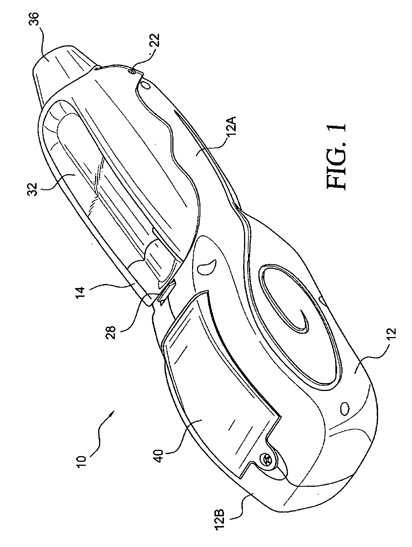
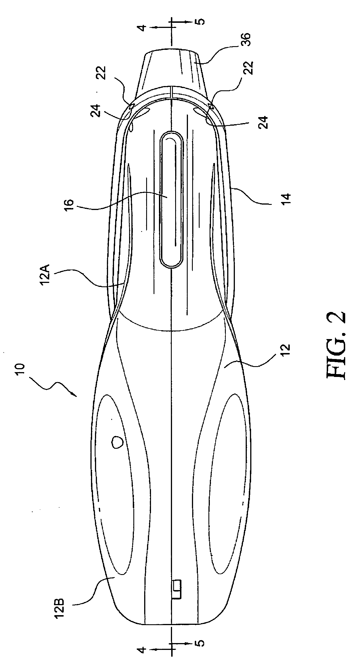
[0019]Referring to the accompanying drawings wherein like reference numbers refer to the same or similar objects, FIG. 1 shows a dispensing apparatus in accordance with the invention for dispensing glitter glue from glitter glue tubes and is designated generally as 10. Dispensing apparatus 10 includes an elongate housing 12, a cover member 14 movably connected to a front portion 12A of the housing 12 and a trigger 16 projecting from a bottom of the front portion 12A of the housing 12 below the cover member 14. Rear portion 12B of the housing 12 has a form which provides for easy manual handling. Housing 12 can be made from two complementary plastic parts 18, 20 and connected together via screws (see FIGS. 4 and 5).

[0020]Cover member 14 is pivotally connected to the housing 12 via pivot pins 22 formed on the front portion 12A of the housing 12 and corresponding apertures 24 formed on the cover member 14 (see FIG. 2). Cover member 14 defines a glitter tube-retaining compartment 26 wit...


PUM


Abstract

Dispensing apparatus for dispensing glue from a tube, such as a glitter glue tube, includes a housing, a cover member movably connected to the housing and defining a tube-receiving compartment with the housing which is opened upon movement of the cover member relative to the housing, an actuatable trigger arranged on the housing, and a compression mechanism arranged in the housing for engaging the tube when in the compartment and compressing the tube upon actuation of the trigger in order to cause glitter glue from the tube to be pushed out of a dispensing opening at a front end of the tube. Actuation of the trigger by the user therefore provides for a controlled dispensing of glue from the tube.

Description

FIELD OF THE INVENTION[0001]The present invention relates generally to a dispensing apparatus for dispensing liquid substances from a tube and more specifically to a dispensing apparatus receivable of a tube of glitter glue and which dispenses the glitter glue in an easily controllable manner.BACKGROUND OF THE INVENTION[0002]In the arts and crafts industry, glitter glue, i.e., glue containing particles of glittering material in different colors, is sold in small, compressible tubes. A front end of the glitter glue tube is provided with a nozzle having a dispensing opening and a thread on an outer surface. A cap is threaded onto the nozzle to cover the dispensing opening. When it is desired to dispense glitter glue from the tube, the cap is removed and the tube is manually squeezed to cause glitter glue in the tube to be dispensed through the dispensing opening.[0003]A significant problem with the manual squeezing of the glitter glue tube is that it is difficult to reliably control t...

Claims


Application Information

Patent Timeline
Patent Type & Authority Applications(United States)
IPC IPC(8): B65D35/28B65D88/54
CPCB05C17/005B65D35/285B05C17/00583
Inventor WIJERAMA, ROSHAN
Owner PNC BANK NAT ASSOC
Learn More