T-slot clamp

a clamp and t-slot technology, applied in the field of clamps, can solve the problems of reducing the life of the clamp, releasing the clamp, and reducing the wear and potential deformation of the clamp components, so as to improve the assembly and manufacturing of the clamp. , the effect of better interchangeability

Inactive Publication Date:
View PDF7 Cites 26 Cited by
  • Summary
  • Abstract
  • Description
  • Claims
  • Application Information

AI Technical Summary

Benefits of technology

[0009] Yet a further object of the present invention may be to provide a T-slot clamp that has better interchangeability which improves assembly and manufacturing of the clamps.

Problems solved by technology

Further, prior art clamps create a holding force by passing the links of the toggle clamps into an over center position, the over center position subjects the links and the pivot points of the clamp to very high loads resulting in increased wear and potential deformation of the clamp components thereby reducing the life of the clamp.
There have been problems with prior art clamps releasing due to vibration and other unforeseen forces during the operations being performed on the work pieces which are held by the clamp.
There also have been problems with the prior art clamps in maintaining a predetermined hold down force needed to keep the objects being held at a precise position such that operations can be performed to predetermined specifications.

Method used


Image

  • T-slot clamp
  • T-slot clamp
  • T-slot clamp

Examples


Embodiment Construction

)

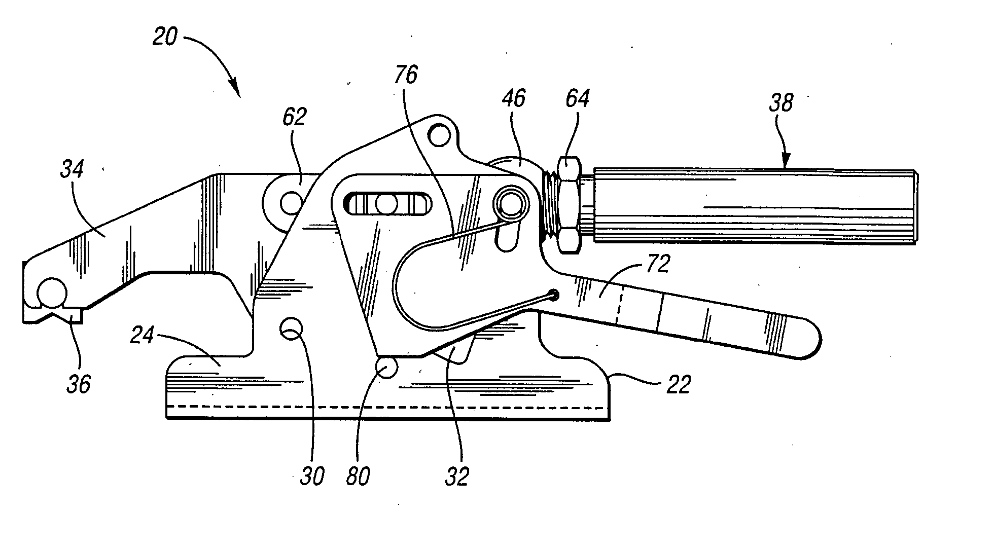
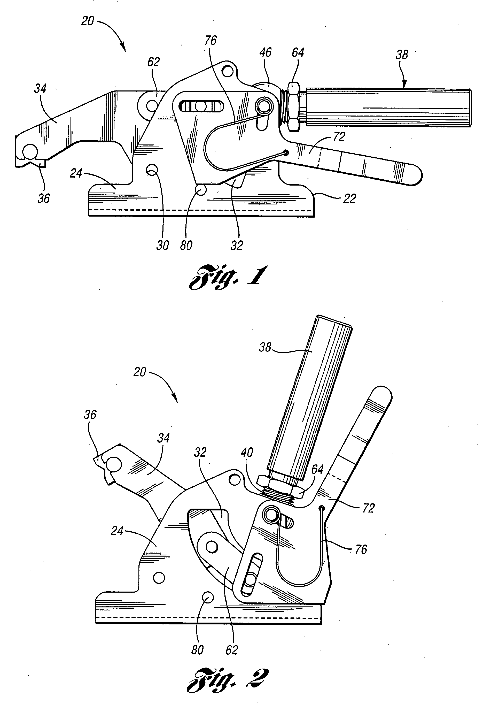
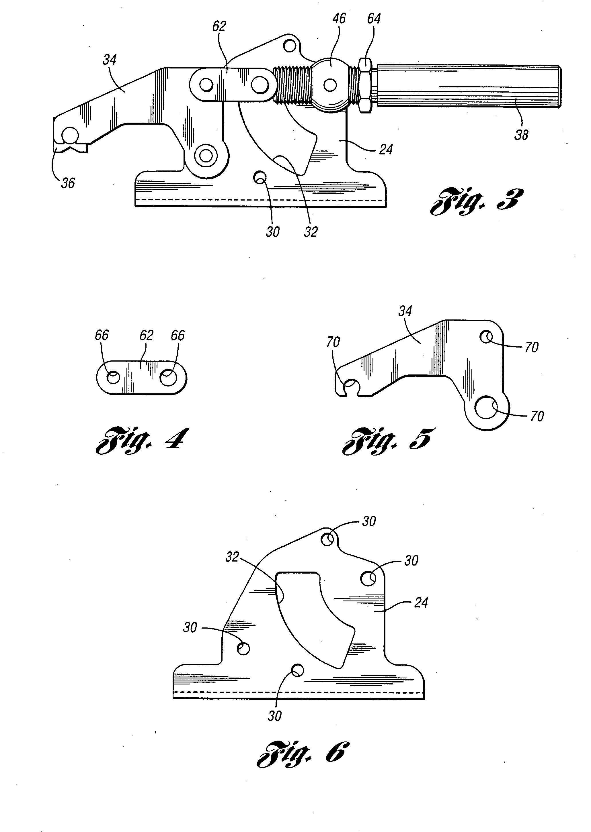
[0034] Referring to the drawings, FIGS. 1 through 15 show an embodiment of a T-slot clamp 20 according to the present invention. It should be noted that the T-slot clamp 20 shown in the drawings is a toggle action locking clamp, however, it may be used in the form of a wedge lock clamp action system and any other known clamping system. It should be noted that the above-identified T-slot clamp 20 is for use in industrial applications with a T-slot table, work surface or other device. However, the clamp 20 can be used in any known push pull clamp, hold down clamp, squeeze clamp, or any other known power or manual clamp or the like used in industrial applications or any other known applications. The present invention may also be used in conjunction with or modified to be used with electronic clamps, hydraulic clamps, or any other known clamp and clamping mechanism. The T-slot clamp 20 according to the present invention generally uses a toggle action to lock the T-slot clamp 20 into it...


PUM


Abstract

A T-slot clamp including a base and a bar member pivotally connected to the base. A link pivotally connected to the bar member. A handle pivotally connected to the link, wherein the handle is rotatable about an axis of the handle.

Description

[0001] This application claims the benefit of provisional application 60 / 801,793 filed May 18, 2006BACKGROUND OF THE INVENTION [0002] This invention broadly relates to clamps. More particularly, this invention relates to a T-slot hold down clamp that is adjustable to various positions in its fully closed or clamped position. [0003] Toggle and hold down clamps have been used and known in the art for many years. The typical hold down or toggle clamp includes a clamping arm which pivots between a released and clamped position. Many of these prior art clamps are used to hold work pieces in place for processing, for clamping two objects to one another, or for clamping an object to a work table or other work surface. Some of these prior art hold down clamps are a variety known as a T-slot clamp, wherein the clamp is arranged within a T-slot arranged on a work surface or work table. The T-slot clamp is held in place within the T-slot via a bolt or other fastener and is capable of sliding a...

Claims


Application Information

Patent Timeline
Patent Type & Authority Applications(United States)
IPC IPC(8): B25B1/14
CPCB25B5/12B25B5/08
Inventor DYKSTRA, HENRY
Why Eureka
Try Eureka