

Illumination system
- Summary
- Abstract
- Description
- Claims
- Application Information
AI Technical Summary
Benefits of technology
Problems solved by technology
Method used
Image

Examples
first embodiment
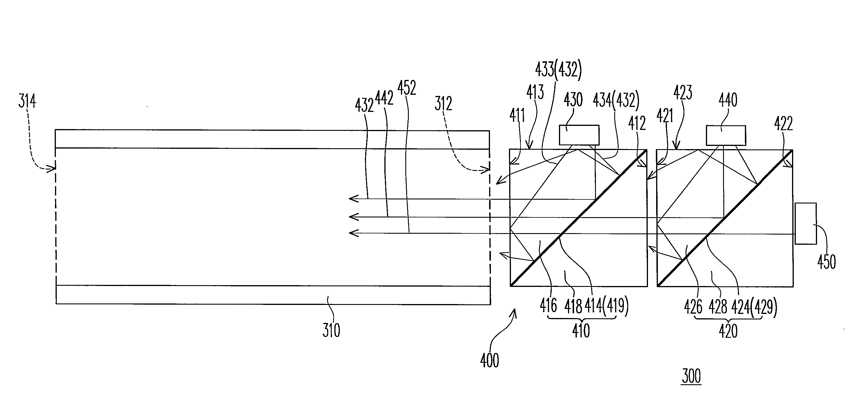
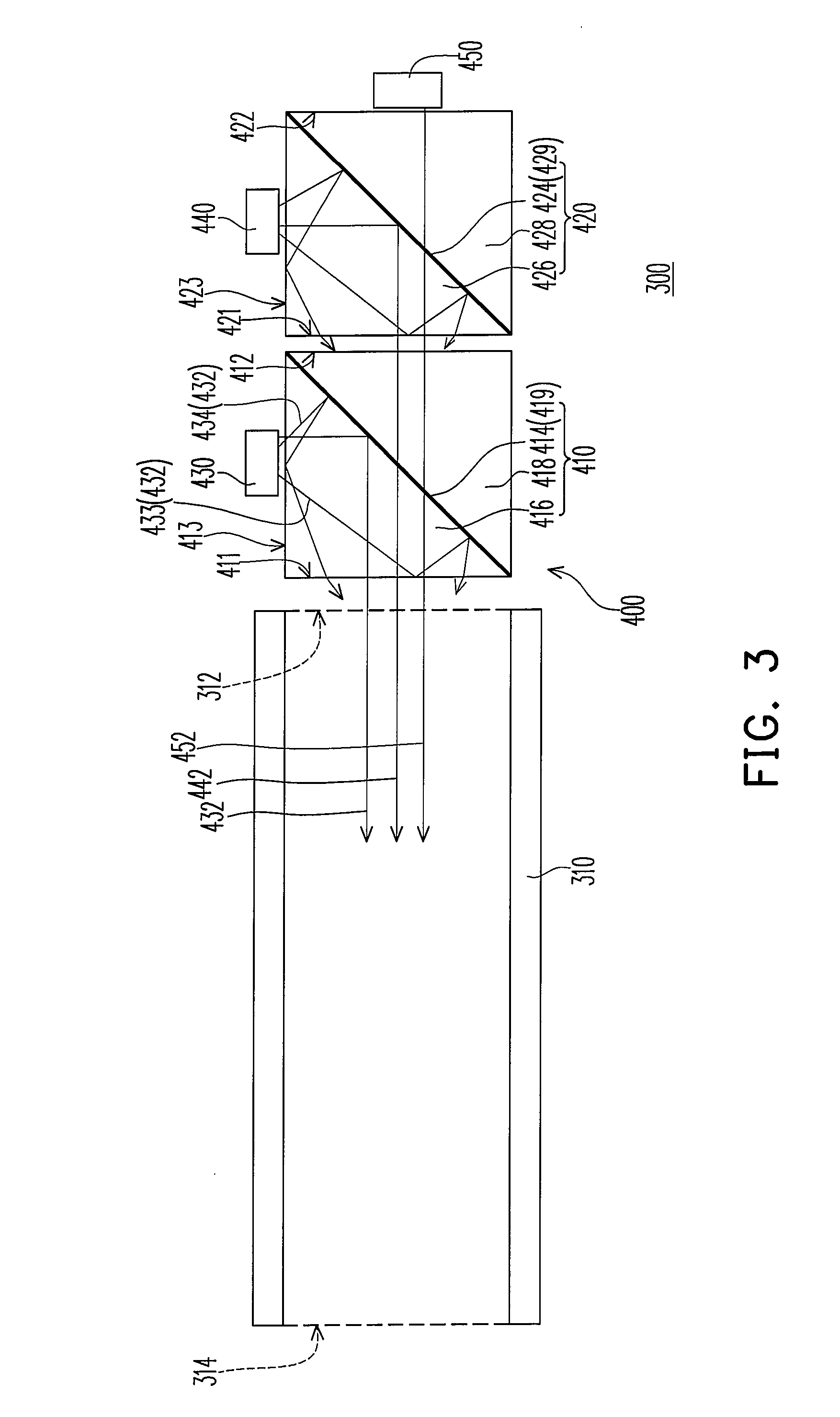
[0023]Referring to FIG. 3, an illumination system 300 in this embodiment comprises a light guide element 310 and a light source device 400. The light guide element 310 has a light incident surface 312 and a light exit surface 314 opposite to the light incident surface 312, and the light source device 400 is disposed adjacent to the light incident surface 312 of the light guide element 310. The light source device 400 comprises a first light combination module 410, a second light combination module 420, a first light source 430, a second light source 440 and a third light source 450. The first light combination module 410 is disposed between the light incident surface 312 of the light guide element 310 and the second light combination module 420. The first light source 430 is disposed adjacent the first light combination module 410, and the second light source 440 and the third light source 450 are disposed adjacent to the second light combination module 420. In addition, the first l...
second embodiment
[0032]Referring to FIG. 6, the illumination system 300d in this embodiment is similar to the illumination system 300 in the first embodiment (as shown in FIG. 3), except that the light source device 400d of the illumination system 300d further comprises a fifth triangular prism 480 and a third coating layer 485. The fifth triangular prism 480 is disposed adjacent to the second bottom surface 422 of the second light combination module 420. The fifth triangular prism 480 has a first rectangular surface 481, a second rectangular surface 482 and a third rectangular surface 483 connecting between the rectangular surface 481 and the second rectangular surface 482. The first rectangular surface 481 is adjacent to the second bottom surface 422, and a gap is disposed between the first rectangular surface 481 and the second bottom surface 422, such that the second bottom surface 422 and the first rectangular surface 481 both are used as total reflection surfaces. In addition, the third light ...
third embodiment
[0037]Referring to FIG. 9, the illumination system 300g in this embodiment is similar to the illumination system 300 in FIG. 3, except the following aspects. In the illumination system 300g, the light source device 400g first light sources 430 and second light sources 440. A number of the first light sources 430 is more than one and a number of the second light sources 440 is more than one. The first light sources 430 are disposed at opposite side of the first light combination module 410g, and the second light sources 440 are disposed at opposite side of the second light combination module 420g. Furthermore, the first light combination module 410g comprises a sixth triangular prism 512, a seventh prism 514 and a first coating layer 516. The sixth triangular prism 512 has three rectangular surfaces, and the first bottom surface 412 of the first light combination module 410g is one of the rectangular surfaces. The seventh prism 514 forms a cubic prism by joining with the other two re...
PUM
 Abstract
Description
Claims
Application Information